Read Sharp AX-1100(R)M / AX-1100(SL)M (serv.man8) Service Manual online
AX1100(R)M
9 – 1
AX1100(R)M
Service Manual
CHAPTER 9.
TEST PROCEDURES
[1] A: MAGNETRON TEST
1. CARRY OUT 3D CHECKS.
2. To test for an open filament, isolate the magnetron from the high voltage circuit. A continuity check across the magnetron filament leads should
indicate less than 1 ohm.
3. To test for a shorted magnetron, connect the ohmmeter leads between the magnetron filament leads and chassis ground. This test should indicate
an infinite resistance. If there is little or no resistance the magnetron is grounded and must be replaced.
4. Reconnect all leads removed from components during testing.
5. Reinstall the outer case (cabinet).
6. Reconnect the power supply cord after the outer case is installed.
7. Run the oven and check all functions.
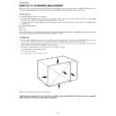
1. MICROWAVE OUTPUT POWER
The following test procedure should be carried out with the microwave oven in a fully assembled condition (outer case fitted).
The power output of this oven is rated using the method specified by IEC 60705. Full details of how to curry out this procedure can be found in the
Sharp Technical Training notes which is available from Sharp Parts Centre (part number SERV-LITMW01).
Sharp Technical Training notes which is available from Sharp Parts Centre (part number SERV-LITMW01).
The IEC60705 procedure must be carried out using laboratory-type procedures and equipment.
These requirements make the procedure unsuitable for routine performance checks.
NOTE: The following test method gives an indication of the output power only, it cannot be used to establish the actual/rated output
power. If the true output power is required, then the IEC60705 test method must be used.
Alternative simplified method:
1. Place 2 litres of cold water (between 12
C and 20C) in a suitable container.
2. Stir the water and measure the temperature in
C. Note temperature as T1.
3. Place the container in the microwave and heat the water for 1 minute and 40 seconds on full power.
4. When the 1 minute and 40 seconds is completed, remove the container and stir the water. Note the water temperature as T2.
5. Calculate the output power using the following formula:
R.F. Power Output = (T2 - T1) x 90.
NOTE: The result from this test should be within the allowance of 2000cc alternative method. (
15%).
2. MICROWAVE LEAKAGE TEST
This oven should be tested for microwave leakage on completion of any repair or adjustment, following the procedure described in the Sharp Techni-
cal Training notes (part number SERV-LITMW01). The maximum leakage permitted in BS EN 60335-2-25 is 50W/m
cal Training notes (part number SERV-LITMW01). The maximum leakage permitted in BS EN 60335-2-25 is 50W/m
2
(equivalent to 5W/m
2
), however
it is not normal to detect any significant leakage, therefore, any leakage which is detected should be investigated.
It is essential that only leakage detectors with current calibration traceable to National Physical Laboratories are used.
Suitable leakage detectors: CELTEC A100
APOLLO X1
[2] B: HIGH VOLTAGE TRANSFORMER TEST
1. CARRY OUT 3D CHECKS.
2. Disconnect the leads to the primary winding of the high voltage transformer. Disconnect the filament and secondary winding connections from the
rest of the HV circuitry. Using an ohmmeter, set on a low range, it is possible to check the continuity of all three winding. The following readings
should be obtained:
should be obtained:
a.Primary winding -------------------- approximately 1.98
b.Secondary winding --------------- approximately 159.5
c.Filament winding --------------------------- less than 1
If the readings obtained are not stated as above, then the high voltage transformer is probably faulty and should be replaced.
3. CARRY OUT 4R CHECKS.
NEVER TOUCH ANY PART IN THE CIRCUIT WITH YOUR HAND OR AN INSULATED TOOL WHILE THE OVEN IS IN OPERATION.
WARNING: High voltages and large currents are present at the secondary winding and filament winding of the power transformer. It is
very dangerous to work near this part when the oven is on. NEVER make any voltage measurements of the high-voltage cir-
cuits, including the magnetron filament.
cuits, including the magnetron filament.
AX1100(R)M
9 – 2
[3] C: HIGH VOLTAGE RECTIFIER TEST
CARRY OUT 3D CHECKS.
Isolate the high voltage rectifier assembly from the HV circuit. The high voltage rectifier can be tested using an ohmmeter set to its highest range.
Connect the ohmmeter across the terminal B+C of the high voltage rectifier and note the reading obtained. Reverse the meter leads and note this
second reading. The normal resistance is infinite in one direction and more than 100 k
Connect the ohmmeter across the terminal B+C of the high voltage rectifier and note the reading obtained. Reverse the meter leads and note this
second reading. The normal resistance is infinite in one direction and more than 100 k
in the other direction.
CARRY OUT 4R CHECKS.
ASYMMETRIC RECTIFIER TEST
CARRY OUT 3D CHECKS.
Isolate the high voltage rectifier assembly from the HV circuit. The asymmetric rectifier can be tested
using an ohmmeter set to its highest range across the terminals A+B of the asymmetric rectifier and
note the reading obtained. Reverse the meter leads and note this second reading. If an open circuit is indicated in both directions then the asymmetric
rectifier is good. If the asymmetric rectifier is shorted in either direction, then the asymmetric rectifier is faulty and must be replaced with high voltage
rectifier. When the asymmetric rectifier is defective, check whether magnetron, high voltage rectifier, high voltage wire or filament winding of the high
voltage transformer is shorted.
CARRY OUT 4R CHECKS.
NOTE: FOR MEASUREMENT OF THE RESISTANCE OF THE RECTIFIER, THE BATTERIES OF THE MEASURING INSTRUMENT MUST HAVE
A VOLTAGE AT LEAST 6 VOLTS, BECAUSE OTHERWISE AN INFINITE RESISTANCE MIGHT BE SHOWN IN BOTH DIRECTIONS.
[4] D: HIGH VOLTAGE CAPACITOR TEST
CARRY OUT 3D CHECKS.
1. Isolate the high voltage capacitor from the circuit.
2. Continuity check must be carried out with measuring instrument which is set to the highest resistance range.
3. A normal capacitor shows continuity for a short time (kick) and then a resistance of about 10M
after it has been charged.
4. A short-circuited capacitor shows continuity all the time.
5. An open capacitor constantly shows a resistance about 10 M
because of its internal 10M resistance.
6. When the internal wire is opened in the high voltage capacitor shows an infinite resistance.
7. The resistance across all the terminals and the chassis must be infinite when the capacitor is normal.
If incorrect reading are obtained, the high voltage capacitor must be replaced.
CARRY OUT 4R CHECKS.
[5] E: SWITCH TEST
CARRY OUT 3D CHECKS.
Isolate the switch to be tested and using an ohmmeter check between the terminals as described in the following table.
If incorrect readings are obtained, make the necessary switch adjustment or replace the switch.
CARRY OUT 4R CHECKS.
[6] F: MONITOR SWITCH TEST
CARRY OUT 3D CHECKS.
Before performing this test, make sure that the monitored interlock switch and the relay RY-4 on the control unit are operating properly, according to
the above Switch Test Procedure. Disconnect the wire lead from the monitor switch (COM) terminal. Check the monitor switch operation by using the
ohmmeter as follows. When the door is open, the meter should indicate a closed circuit. When the monitor switch actuator is pushed by a screw driver
through the right latch hole on the front plate of the oven cavity with the door opened (in this condition the plunger of the monitor switch is pushed in),
the meter should indicate an open circuit. If improper operation is indicated, the switch may be defective. After testing the monitor switch, reconnect
the wire lead to the monitor switch (COM) terminal and check the continuity of the monitor circuit.
CARRY OUT 4R CHECKS.
[7] G: THERMISTOR TEST
CARRY OUT 3D CHECKS.
Disconnect the thermistor from the control unit. Measure the resistance of the thermistor with an ohmmeter.
If the meter does not indicate above resistance, replace the thermistor. CARRY OUT 4R CHECKS.
Table: Terminal Connection of Switch
Plunger Operation
Common terminal to Normally open terminal
Common terminal to Normally close terminal
Released
Open circuit
Short circuit
Depressed
Short circuit
Open circuit.
Room Temperature
25
C
100
C
200
C
Resistance
Approximately 200 k
Approximately 10 k
Approximately 1 k
D2
D1
ASYMMETRIC
RECTIFIER
HIGH VOLTAGE
RECTIFIER
A
B
C
AX1100(R)M
9 – 3
[8] H: THERMAL CUT-OUT TEST
CARRY OUT 3D CHECKS.
Disconnect the leads from the terminals of the thermal cut-out. Then using an ohmmeter, make a continuity test across the two terminals as described
in the below.
in the below.
If incorrect readings are obtained, replace the thermal cut-out.
An open circuit thermal cut-out (MG) TC1 indicates that the magnetron has overheated, this may be due to resistricted ventilation, cooling fan failure.
An open circuit thermal cut-out (OVEN) TC2 indicates that the oven cavity has overheated, this may be due to no load operation or fire in the oven
cavity.
cavity.
An open circuit thermal cut-out (Engine) TC3 indicates that the engine unit has overheated, this may be due to empty water tank or pump motor fail-
ure.
ure.
CARRY OUT 4R CHECKS.
[9] I: BLOWN FUSE (F1) 20A
CARRY OUT 3D CHECKS.
If the fuse F1 20A is blown, there is a shorts or grounds in electrical parts or wire harness. Check them and replace the defective parts or repair the
wire harness.
wire harness.
CARRY OUT 4R CHECKS.
CAUTION: Only replace fuse with the correct value replacement.
[10] J: BLOWN FUSE (F2) F8A (NOISE FILTER)
CARRY OUT 3D CHECKS.
1. If the fuse F2 F8A is blown when the door is opened, check the monitored interlock switch and monitor switch.
2. If the fuse F2 F8A is blown by incorrect door switching replace the defective switch(es) and the fuse F2 F8A.
3. If the fuse F2 F8A is blown, there could be shorts in the asymmetric rectifier or there is a ground in wire harness. A short in the asymmetric rectifier
may be occurred due to short or ground in H.V. rectifier, magnetron, high voltage transformer or H.V. wire. Check them and replace the defective
parts or repair the wire harness.
parts or repair the wire harness.
CARRY OUT 4R CHECKS.
[11] K: NOISE FILTER TEST
CARRY OUT 3D CHECKS.
Disconnect the leads from the terminals of the noise filter. Using an ohmmeter, check
between the terminals as described in the following table.
between the terminals as described in the following table.
If incorrect readings are obtained, replace the noise filter unit.
CARRY OUT 4R CHECKS.
[12] L: GRILL HEATING ELEMENTS (TOP) AND
ENGINE HEATING ELEMENT TEST
ENGINE HEATING ELEMENT TEST
CARRY OUT 3D CHECKS.
Before carrying out the following tests make sure the heating element is cool completely.
1. Resistance of heater.
Disconnect the wire leads to the heating element to be tested. Using ohmmeter with low resistance range. Check the resistance across the termi-
nals of the heating element as described in the following table.
nals of the heating element as described in the following table.
Table: Thermal Cut-out Test
Parts Name
Temperature of “ON” condition
(closed circuit)
Temperature of “OFF” condition
(open circuit)
Indication of ohmmeter (When room
temperature is approx. 20
temperature is approx. 20
C.)
Thermal cut-out TC1 145
C
Bellow -20
C
Above 145
C
Closed circuit
Thermal cut-out TC2, TC3
Bellow -20 or -35
C.
Above 170
C
Closed circuit
MEASURING POINT
INDICATION OF OHMMETER
Between N and L
Approx. 680 k
Between terminal N and WHITE
Short circuit
Between terminal L and RED
Short circuit
Table: Resistance of heater
Parts name
Resistance
Grill heating element
Approximately 46.5 ~ 51.1
Engine heating element
Approximately 58.0 ~ 62.9
F2: F8A
20A
WHT
RED
R1
R2
N
Cx
Cy
L
L
L
L (min) Cx ± 20% Cy ± 20%
R1
R2
1.0mH
0.22 uF
4700pF 10 M
680k
AX1100(R)M
9 – 4
2. Insulation resistance.
Disconnect the wire leads to the heating element to be tested. Check the insulation resistance between the element terminal and cavity using a
500V - 100M
500V - 100M
insulation tester. The insulation resistance should be more than 10M in the cold start.
If the results of above test 1 and/or 2 are out of above specifications, the heating element is probably faulty and should be replaced.
CARRY OUT 4R CHECKS.
[13] M: CONTROL UNIT TEST
The control unit consists of circuits including semiconductors such as LSI, ICs, etc. Therefore, unlike conventional microwave ovens, proper mainte-
nance can not be performed with only a voltmeter and ohmmeter.
nance can not be performed with only a voltmeter and ohmmeter.
In this service manual, the control panel assembly is divided into two units, Control Unit and Key Unit, and troubleshooting by replacement is
described according to the symptoms indicated.
described according to the symptoms indicated.
1. Key Unit Note: Check Key unit ribbon connection before replacement.
The following symptoms indicate a defective key unit. Replace the key unit.
1) When touching the pads, a certain pad produces no signal at all.
2) When touching a number pad, two figures or more are displayed.
3) When touching the pads, sometimes a pad produces no signal.
2. Control Unit
The following symptoms indicate a defective control unit. Before replacing the control unit perform the key unit test (Procedure N) to determine if con-
trol unit is faulty.
trol unit is faulty.
2.1. In connection with pads
1) When touching the pads, a certain group of pads do not produce a signal.
2) When touching the pads, no pads produce a signal.
2.2. In connection with indicators
1) At a certain digit, all or some segments do not light up.
2) At a certain digit, brightness is low.
3) Only one indicator does not light up.
4) The corresponding segments of all digits do not light up; or they continue to light up.
5) Wrong figure appears.
6) A certain group of indicators do not light up.
7) The figure of all digits flicker.
2.3. Other possible troubles caused by defective control unit.
1) Buzzer does not sound or continues to sound.
2) Clock does not operate properly.
3) Cooking is not possible.
4) Proper temperature measurement is not obtained.
[14] N: KEY UNIT (MEMBRANE SWITCH) TEST
If the display fails to clear when the STOP key is depressed, first verify the rib-
bon cable is making good contact, verify that the door sensing switch operates
properly; that is the contacts are closed when the door is closed and open when
the door is open. If the door sensing switch is good, disconnect the flat ribbon
cable that connects the key unit to the control unit and make sure the door sens-
ing switch is closed (either close the door or short the door sensing switch con-
nector). Use the Key unit matrix indicated on the control panel schematic and
place a jumper wire between the pins that correspond to the STOP key making
momentary contact. If the control unit responds by clearing with a beep the key
unit is faulty and must be replaced. If the control unit does not respond, it is a
faulty and must be replaced. If a specific pad does not respond, the above
method may be used (after clearing the control unit) to determine if the control
unit or key pad is at fault.
CARRY OUT 4R CHECKS.

