Read Sharp UP-V5500 (serv.man21) Technical Bulletin online
E
E
C
C
R
R
/
/
E
E
P
P
O
O
S
S
T
T
e
e
c
c
h
h
n
n
i
i
c
c
a
a
l
l
S
S
u
u
p
p
p
p
o
o
r
r
t
t
Sharp Technical Update
1 of 5
The following information should be used to fit the UPV5500MCR to the
UPV5500 terminal and also configure the MCR Parameters.
Fitting the MCR.
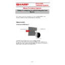
1) Removal of MCR Cover 2
Important Remove Mains power prior to installing the MCR
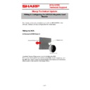
The 2 screws A) should be removed by using Philips head screwdriver, and
the MCR rear cover2 should be opened toward the direction of B) red arrow.
(MCR Cover2 is the cover for the unused MCR.)
The 2 screws A) should be removed by using Philips head screwdriver, and
the MCR rear cover2 should be opened toward the direction of B) red arrow.
(MCR Cover2 is the cover for the unused MCR.)
Fitting & Configuring the UP5500 Magnetic Card
Reader
E
E
C
C
R
R
/
/
E
E
P
P
O
O
S
S
T
T
e
e
c
c
h
h
n
n
i
i
c
c
a
a
l
l
S
S
u
u
p
p
p
p
o
o
r
r
t
t
Sharp Technical Update
2 of 5
2) Attachment of the MCR Controller
After attaching controller using 2 screws, connect B) connector.
3) MCR Module attachment.
Insert MCR Module toward the direction of the arrow as in above picture B)
Groove.
After attaching controller using 2 screws, connect B) connector.
3) MCR Module attachment.
Insert MCR Module toward the direction of the arrow as in above picture B)
Groove.
E
E
C
C
R
R
/
/
E
E
P
P
O
O
S
S
T
T
e
e
c
c
h
h
n
n
i
i
c
c
a
a
l
l
S
S
u
u
p
p
p
p
o
o
r
r
t
t
Sharp Technical Update
3 of 5
4) MCR Connector Connection.
Tighten Screw A) and connect connector B)
5) Closing the MCR cover1.
Close MCR cover 1 and tighten the 2 screws A).
MCR cover1 is the cover for the used MCR
E
E
C
C
R
R
/
/
E
E
P
P
O
O
S
S
T
T
e
e
c
c
h
h
n
n
i
i
c
c
a
a
l
l
S
S
u
u
p
p
p
p
o
o
r
r
t
t
Sharp Technical Update
4 of 5
MCR - OPOS software configuration.
In order for the UPV5500 to communicate correctly to the MCR via OPOS the
following procedure must be performed.
1.
Ensure that the MCR hardware has been correctly installed.
2.
Power on the UPV5500
3.
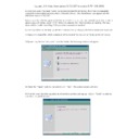
From within Windows select – Start – All Programs – VCT OPOS Drivers
– Tools – MSR Configuration
4.
From within the MSR configuration Tool, Select File – Setting – ensure
that the Port=COM7 and the Baudrate=19200
5.
From the main MSR Configuration Tool screen ensure that the settings
are shown as above (these should be already set)
6.
Select the ‘Write the setting’ button.

