Read Sharp UP-V5500 (serv.man2) Handy Guide online
E
E
C
C
R
R
/
/
E
E
P
P
O
O
S
S
T
T
e
e
c
c
h
h
n
n
i
i
c
c
a
a
l
l
S
S
u
u
p
p
p
p
o
o
r
r
t
t
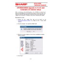
UPV5500 BIOS Upgrade to V1.01 and
External LCD monitor setup
1 of 4
When connecting an external LCD monitor to the UPV5500 it has been found
that only some displays are compatible, this is due to the UPV5500 Bios. The
following information will guide you through the Bios update procedure and
explain how to enable the UPV5500 to work with an External LCD monitor.
Bios Update Procedure
that only some displays are compatible, this is due to the UPV5500 Bios. The
following information will guide you through the Bios update procedure and
explain how to enable the UPV5500 to work with an External LCD monitor.
Bios Update Procedure
1.
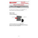
Extract the Bios update files that can be found on the
www.tradenet.sharp.co.uk/tech
to a folder on the C: drive within
windows.
2.
From the extracted files select the AFUWIN.EXE
3.
When the warning is displayed close all open applications including
explorer windows
4.
Click “Open”
E
E
C
C
R
R
/
/
E
E
P
P
O
O
S
S
T
T
e
e
c
c
h
h
n
n
i
i
c
c
a
a
l
l
S
S
u
u
p
p
p
p
o
o
r
r
t
t
UPV5500 BIOS Upgrade to V1.01 and
External LCD monitor setup
2 of 4
5.
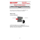
Select BIOS Image file X700V101.rom, Click Open.
6.
Select the Setup Tab and tick the following options “Program All
Blocks, Destroy CMOS Checksum, Restart after Programming.
E
E
C
C
R
R
/
/
E
E
P
P
O
O
S
S
T
T
e
e
c
c
h
h
n
n
i
i
c
c
a
a
l
l
S
S
u
u
p
p
p
p
o
o
r
r
t
t
UPV5500 BIOS Upgrade to V1.01 and
External LCD monitor setup
3 of 4
7.
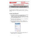
Important! Ensure that the above setup options are enabled.
8.
Click “Flash”, the BIOS update will now be executed.
9.
Do not use computer whilst the “Flash” procedure is running.
10.
Do not turn off power whilst the new Rom is being written.
11.
After completing the writing of the new ROM the UPV5500 will restart
automatically.
12.
After restart select F2 to ‘load default Bios values and continue’.
13.
The Bios update is now completed.
E
E
C
C
R
R
/
/
E
E
P
P
O
O
S
S
T
T
e
e
c
c
h
h
n
n
i
i
c
c
a
a
l
l
S
S
u
u
p
p
p
p
o
o
r
r
t
t
UPV5500 BIOS Upgrade to V1.01 and
External LCD monitor setup
4 of 4
Windows Display Settings
1.
Ensure that the external display / TV is powered on and connected to the
UPV5500 via the VGA port at the back of the UPV5500 using a standard
VGA cable.
VGA cable.
2.
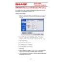
Advanced – ‘Intel® Graphics Media Accelerator Driver for Mobile’ –
Graphics Properties – Display Devices or simply press (Ctrl) (ALT) (F12)
Graphics Properties – Display Devices or simply press (Ctrl) (ALT) (F12)
3.
Select Multiple Display
4.
Select Intel® Dual Display Clone
5.
Set the Primary Device to Notebook
6.
Set the Secondary Device to Monitor
7.
Select Apply
8.
Press the following key sequence (Ctrl) (ALT) (F3) to switch between the
external second display and the UPV5500 display or both displays.
9.
The TV used to test this is the Sharp LC-22LE320E, the LCD monitor used
to test is the Sharp LL-H1513-H

