Read Sharp OPTIONS (serv.man31) Technical Bulletin online
PR-58L PRINTER FOR ER-01PU
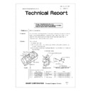
CORRECTIVE MEASURE AGAINST HOUSING
PULLEY GEAR SHAFT BREAKAGE
CORRECTIVE MEASURE AGAINST HOUSING
PULLEY GEAR SHAFT BREAKAGE
ELECTRONIC CASH REGISTER: ER-01PU
Brown
C
Date : Oct. 27, 1997
No. : ECR-1113
1. Model name:
ER-01PU (KA/KB/TQ)
2. General:
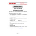
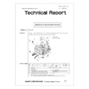
Due to a failure in molding process for housing, the housing pulley gears shaft may
break. To correct this problem, the stem of the gear shaft is reinforced. At the
same time, the corrective parts: S-Angles for reinforcement and S-Pins for
replacement are made available as repair parts.
3. Action:
((For the field))
<To correct field units>
(1) For the units without the shaft breakage: Reinforce the shaft by attaching an
S-Angle (reinforcing plate).
(2) For the units with the shaft breakage: Replace the shaft with an S-Pin and also
add an S-Angle.
1/4
Personal Computer Division
SHARP CORPORATION
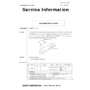
Paper chute
(2) SCREW (M3
×
8)
(1) S-AHGLE
(3) S-PIN
Pulley gear shaft (Broken part)
PR-58L Printer housing
Magnified view of A Parts to be supplied to the field
(4) SCREW (M3
×
6)
ER-01PU [A]
Auto cutter
Take-up spool
Paper roll location
Release lever
Parts to be supplied to the field
No.
Parts Code
Parts Name
Q’ty
Note
(1)
LANGT2776BHZZ
S-Angle
1pc.
Combination of (1) and (2)
(2)
LX-BZ1085CCZZ
Screw (M3
×
8)
1pc.
Combination of (1) and (2)
(3)
LPINZ2321BHZZ
S-Pin
1pc.
Combination of (3) and (4)
(4)
XBPSD30P06KSO
Screw (M3
×
6)
1pc.
Combination of (3) and (4)
1) For the units without pulley gear shaft breakage
(Corrective parts to be used)
(How to attach corrective parts) Fig:1
(1) From the side of the printer journal, remove the screw(5) (M3
×
8KS) using a
cross-bladed screwdriver, and then attach S-Angle(1) (LANGT2776BHZZ).
(2) To secure the S-Angle(1), use a longer screw(2) (M3
×
8) (LX-BZ1085CCZZ)
in replace of the original screw(6) (M3
×
5).
(3) Tighten the screw(5) (M3
×
8KS).
No.
Parts Code
Parts Name
Q’ty
(1)
LANGT2776BHZZ
S-Angle
1pc.
(2)
LX-BZ1085CCZZ
Screw (M3
×
8)
1pc.
PULLEY GEAR
(1) S-ANGLE
(2) SCREW (M3
×
8)
(5) SCREW (M3
×
8KS)
TIMING BELT
(1) S-ANGLE
(5) SCREW (M3
×
8KS)
LEVER
(2) SCREW (M3
×
8)
(6) SCREW (M3
×
5)
View with lever removed for explanation Magnified view
<Fig:1>
2) For the units with pulley gear shaft breakage
(Corrective parts to be used)
(How to attach corrective parts)
(1) Before starting modification, put a screw(4) (XBPSD30P06KSO) into the
S-Pin(2) (LPINZ2321BHZZ).
(2) Remove burrs from the printer housing at broken part by rubbing with a
sanding paper to flat the surface.
(3) Insert the S-Pin(2) (LPINZ2321BHZZ) and the Screw(4) (XBPSD30P06KSO)
into the housing using a cross-bladed driver. Ensure to insert the S-Pin(2)
fully to its stem perpendicular to the housing surface.
(4) If screwdriver is turned in reverse direction, only Screw(4)
(XBPSD30P06KSO) comes off.
(5) Mount the pulley gear(7) and check if it rotates smoothly without any problem
with the pitch of both gears. After the check, apply grease to the S-Pin.
(6) Attach pulley gear(7), washer(8), and timing belt(9).
No.
Parts Code
Parts Name
Q’ty
(1)
LANGT2776BHZZ
S-Angle
1pc.
(2)
LPINZ2321BHZZ
S-Pin
1pc.
(3)
LX-BZ1085CCZZ
Screw (M3
×
8)
1pc.
(4)
XBPSD30P06KSO
Screw (M3
×
6)
1pc.
2/4
(7) Mount S-Angle(1) (LANGT2776BHZZ) using a screwdriver.
(8) Use longer screw(2) (M3
×
8 LX-BZ1085CCZZ) instead of screw(6) (M3
×
5)
to fix the S-Angle(1).
(9) Tighten the screw(4) (M3
×
6) instead of original screw(5) (M3
×
8KS).
Printer housing
(4) SCREW
(2) S-PIN
Cross-bladed screwdriver
Other original parts such as pulley gear are to be used again
Steps (1)~(3) of mounting procedure
(7) PULLEY GEAR
(1) S-ANGLE
(2) SCREW (M3
×
8)
(4) SCREW (M3
×
6)
(9) TIMING BELT
(1) S-ANGLE
(4) SCREW (M3
×
6)
(5) SCREW (M3
×
8KS)
LEVER
(2) SCREW (M3
×
8)
(6) SCREW (M3
×
5)
View with lever removed for explanation Magnified view
Steps (6)~(9) of mounting procedure
<Fig:2>
(7) PULLEY GEAR
(8) WASHER
((For the production))
Housing shape is changed to strengthen the stem of the pulley gear shaft.
Housing shape is changed starting from the 1st unit of July, 1997 production.
New housings are compatible with original ones.
Cross-cut of original shaft Cross-cut of modified shaft
3/4
4. Parts change:
Ref
No.
No.
Model
name
name
Version
P/G No.
Current parts
New parts
Parts name
Effec-
tive
time
tive
time
Inter-
change-
ability
change-
ability
Note
Parts code
Parts code
Price
rank
1
ER-01PU
KA/KB/TQ
—
—
LANGT2776BHZZ
AY
S-Angle
Jul. ’97
6
0
→
1
—
LX-BZ1085CCZZ
AA
Screw (M3
×
8)
—
LPINZ2321BHZZ
AM
S-Pin
—
XBPSD30P06KSO
AA
Screw (M3
×
6)
<Interchange>
1. Interchangeable.
4. Not interchangeable.
2. Current type can be used in place of new type.
New type cannot be used in place of current type.
5. Interchangeable if replaced with same types of
related parts in use.
3. Current type cannot be used in place of new type.
New type can be used in place of current type.
6. Others.
Parts marked with " ! " is important for maintaining the safety of the set.
Be sure to replace these parts with specified ones for maintaining the safety and performance of the set.
Be sure to replace these parts with specified ones for maintaining the safety and performance of the set.
4/4

