Read Sharp DV-SL10H (serv.man8) Service Manual online
1-7-1
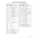
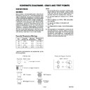
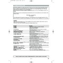
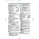
TESTMODE
TEST MODE
Test Mode
ROM Renewal Mode
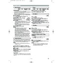
A power source is put, and [1], [2], [3], [4], and [ON SCREEN] buttons on the remote
control unit are pushed in that order while the tray is opening or after the “NO DISC”
display at the same time.
control unit are pushed in that order while the tray is opening or after the “NO DISC”
display at the same time.
A power source is put, and [9], [8], [7], [6], and [DIRECT SKIP] buttons on the remote
control unit are pushed in that order while the tray is opening or after the “NO DISC”
display at the same time.
control unit are pushed in that order while the tray is opening or after the “NO DISC”
display at the same time.
[TEST MODE]
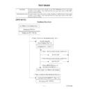
Test Mode Flow Chart
Test Mode Initial Display (Fig.T-1)
Displaying F/W Ver.
Displaying VFD F/W Ver.
< Press 1 button on the remote control unit. >
< Press 1 button on the remote control unit. >
< Press 2 button on the remote control unit. >
< Press 3 button on the remote control unit. >
< Press RETURN button on
the remote control unit. >
Returning to Test Mode Initial Display
All VFD ON/OFF
Menu Display (Fig. T-2)
Cearing FLASH MEMORY (Fig. T-3)
All VFD ON
All VFD OFF
Displaying VFD "TEST1"
Displaying VFD "TEST3"
1-7-2
TESTMODE
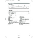
Fig. T-1: Test Mode Initial Display
Fig. T-2: All VFD ON/OFF Menu Display
Fig. T-3: Clearing FLASH MEMORY Display
(model name) VERSION
REGION
1. TEST1-VFD
2. TEST2-REPEAT PLAY
2. TEST2-REPEAT PLAY
3.
TEST3-
EEPROM CLEAR
4.
TEST4-
MEASUREMENT SERVO
5.
TEST5-
DISC READ CHECK
6.
TEST6-
MECHA CHECK
7.
TEST7-
DISC INFO
8.
TEST8-
ERROR RATE
EXIT:
.
(model name) VERSION
REGION
TEST1-VFD
1. ON
2. OFF
1. ON
2. OFF
VFD STATUS [---]
RETURN:
.
POWER
(model name) VERSION
REGION
TEST3-EEPROM CLEAR
EEPROM CLEAR : OK
EXIT:
.
POWER
EXIT:
POWER
RETURN
1-7-3
TESTMODE
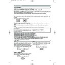
[ROM RENEWAL MODE]
1. Turn the power on and remove the disc on the tray.
2. To put the DVD player into version up mode, press
2. To put the DVD player into version up mode, press
[9], [8], [7], [6], and [DIRECT SKIP] buttons on the
remote control unit in that order. The tray will open
automatically.
Fig. a appears on the screen and Fig. b appears on
the VFD.
remote control unit in that order. The tray will open
automatically.
Fig. a appears on the screen and Fig. b appears on
the VFD.
F/W Version Up Mode
Please insert a DISC
for F/W Version Up.
EXIT: POWER
Fig. a Version Up Mode Screen
Fig. b VFD in Version Up Mode
The DVD player can also enter the version up mode
with the tray open. In this case, Fig. a will be shown
on the screen while the tray is open.
with the tray open. In this case, Fig. a will be shown
on the screen while the tray is open.
3. Load the disc for version up.
4. The DVD player enters the F/W version up mode
4. The DVD player enters the F/W version up mode
automatically. Fig. c appears on the screen and
Fig. d appears on the VFD.
Fig. d appears on the VFD.
F/W Version Up Mode
VERSION : ********
Reading...(*2)
Reading...(*2)
EXIT: POWER
Fig. c Programming Mode Screen
Fig. d VFD in Programming Mode (Example)
The appearance shown in (*2) of Fig. c is described
as follows:
as follows:
Appearance
No.
State
Reading...
Sending files into the memory
Erasing...
Erasing previous version data
Programming...
1
2
3
Writing new version data
5. After programming is finished, the tray opens auto-
matically. Fig. e appears on the screen and the
checksum in (*3) of Fig. e appears on the VFD. (Fig. f)
checksum in (*3) of Fig. e appears on the VFD. (Fig. f)
F/W Version Up Mode
VERSION : ********
Completed
Completed
SUM : 7abc (*3)
Fig. e Completed Program Mode Screen
Fig. f VFD upon Finishing the Programing Mode (Example)
At this time, no buttons are available.
6. Unplug the AC cord from the AC outlet. Then plug it
again.
7. Turn the power on by pressing the power button and
the tray will close.
8. Press [1], [2], [3], [4], and [DIRECT SKIP] buttons on
the remote control unit in that order.
Fig. g appears on the screen.
Fig. g appears on the screen.
model: ******
Ver: ****
Region: **
1: VFD TEST
2: TT REPEAT PLAY
2: TT REPEAT PLAY
3: EEPROM CLEAR
4: MEASUREMENT SERVO
5: DISC READ CHECK
6: MECHA CHECK
7: DISC INFO
8: ERROR RATE
4: MEASUREMENT SERVO
5: DISC READ CHECK
6: MECHA CHECK
7: DISC INFO
8: ERROR RATE
EXIT: POWER
RETURN: -----
Fig. g
9. Press [3] button on the remote control unit.
Fig. h appears on the screen.
model: ******
Ver: ****
Region: **
TEST 3: EEPROM CLEAR
EEPROM CLEAR: OK
EEPROM CLEAR: OK
EXIT: POWER
RETURN: -----
Fig. H
10.To finish this mode, press [POWER] button.
1-7-4
TESTMODE
[ ERROR RATE MEASUREMENT]
1. Turn on the power to the player, remove the disk
from the tray, and close the tray.
2. To put the DVD player into test mode, press [1], [2],
[3], [4], and [ON SCREEN] buttons on the remote
control unit in that order.
The unit will switch to Test Mode and Fig. a will be
displayed. For VFD, the current F/W version will be
displayed. (Fig. b)
control unit in that order.
The unit will switch to Test Mode and Fig. a will be
displayed. For VFD, the current F/W version will be
displayed. (Fig. b)
(model name) VERSION
REGION
1. TEST1-VFD
2. TEST2-REPEAT PLAY
2. TEST2-REPEAT PLAY
3.
TEST3-
EEPROM CLEAR
4.
TEST4-
MEASUREMENT SERVO
5.
TEST5-
DISC READ CHECK
6.
TEST6-
MECHA CHECK
7.
TEST7-
DISC INFO
8.
TEST8-
ERROR RATE
EXIT:
.
POWER
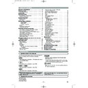
Fig. a Test Mode Screen
Fig. b Sample VFD in Test Mode
3. Press the [8] button to select "8. TEST 8 - ERROR
RATE." The on-screen display will change to the
screen shown in Fig. c. The VDF display will change
to the display shown in Fig. d.
screen shown in Fig. c. The VDF display will change
to the display shown in Fig. d.
(model name) VERSION
REGION
TEST8-ERROR RATE
DISC:DVD-V / DUAL LAYER / OPPOSITE
STA:
STATUS:
CHECK : OK
NOW MEASURE : L
DISC:DVD-V / DUAL LAYER / OPPOSITE
STA:
STATUS:
CHECK : OK
NOW MEASURE : L
RETURN:
.
EXIT:
POWER
RETURN
1
5
H
/
2
H
H
/
3
H
/
4
H
PO1st
00000 00000 00000 00000 00000
00000 00000 00000 00000 00000
00000 00000 00000 00000 00000
Correct
Uncorrect
PI1st
PO2nd
PO3rd
PI2nd
(I) With a DVD inserted.
(model name) VERSION
REGION
TEST8-ERROR RATE
DISC: CD
STA:
STATUS:
CHECK : OK
NOW MEASURE :
DISC: CD
STA:
STATUS:
CHECK : OK
NOW MEASURE :
RETURN:
.
EXIT:
POWER
RETURN
5
H
TRK
:
:
00000
00000
00000
C1 Correct
C2 Uncorrect
C2 Uncorrect
:
:
(II) With a CD/VCD inserted.
Fig. c TEST8-ERROR RATE MODE
Fig. d Sample VFD in TEST8-ERROR RATE MODE
4. Put disk to be checked into the tray. Close the tray
using either the [OPEN/CLOSE] or [PLAY] button on
the unit or on the remote. The disk will automatically
be distinguished and error rate measurement will
begin.
Fig. c will display:
the unit or on the remote. The disk will automatically
be distinguished and error rate measurement will
begin.
Fig. c will display:
1
Inserted disk’s inner parameter (For DVD, Layer
0, initial address)
0, initial address)
2
Inserted disk’s outer parameter (For DVD, Layer
0, final address)
0, final address)
3
Inserted disk’s Layer 1, initial address.
4
Inserted disk’s Layer 1, final address.
Depending on the contents of the inserted disk, 3
and 4 above may not be displayed.
Once the error rate measurement has started, if the
largest value resulting from the first three measure-
ments has a value of 2000 or less, and all values in
the "Uncorrect" row are 0, the message "CHECK :
OK" will be displayed on area
and 4 above may not be displayed.
Once the error rate measurement has started, if the
largest value resulting from the first three measure-
ments has a value of 2000 or less, and all values in
the "Uncorrect" row are 0, the message "CHECK :
OK" will be displayed on area
5
.
If the largest value is greater than 2000, the mes-
sage "CHECK : NG" will be displayed on area
sage "CHECK : NG" will be displayed on area
5
.
5. "Correct" and "Uncorrect" in Fig. c:
(1) For DVDs the following will be displayed:
PO1st-Correct count; PO1st-Uncorrect count;
PI1st-Correct count; PI1st-Uncorrect count;
PO2nd-Correct; PO2nd-Uncorrect count;
PI2nd-Correct count; PI2nd-Uncorrect count;
PO3rd-Correct count; PO3rd-Uncorrect count.
The above ten numerical values will be displayed for
each 80 ECC block.
PO1st-Correct count; PO1st-Uncorrect count;
PI1st-Correct count; PI1st-Uncorrect count;
PO2nd-Correct; PO2nd-Uncorrect count;
PI2nd-Correct count; PI2nd-Uncorrect count;
PO3rd-Correct count; PO3rd-Uncorrect count.
The above ten numerical values will be displayed for
each 80 ECC block.
(2) For CD/VCDs the following will be displayed:
C1-Correct count; C2-Uncorrect count.
The values for these two items will be displayed
every 7350x4 frames.
For VFD, the following will be displayed:
PO1st-Correct count; (C1-Correct count for CDs).
(Fig. e)
C1-Correct count; C2-Uncorrect count.
The values for these two items will be displayed
every 7350x4 frames.
For VFD, the following will be displayed:
PO1st-Correct count; (C1-Correct count for CDs).
(Fig. e)
Fig. e: Sample VFD display of ERROR RATE
measurement
measurement
6. To end the ERROR RATE measurement, press the
[OPEN/CLOSE] button on either the unit or the
remote. After the display has ceased, press the
[POWER] button on either the unit or the remote to
shut off the power.
remote. After the display has ceased, press the
[POWER] button on either the unit or the remote to
shut off the power.

