Read Sharp DV-S1 (serv.man7) Service Manual online
1-8-1
E56H0TS
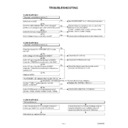
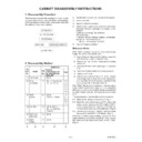
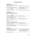
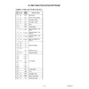
TROUBLESHOOTING
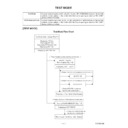
FLOW CHART NO.1
FLOW CHART NO.2
The power cannot be turned on.(1)
FLOW CHART NO.3
The fuse blows out.
After servicing, replace the fuse.
The power cannot be turned on.(2)
Is the fuse normal?
Is normal state restored when once unplugged
power cord is plugged again after several seconds?
power cord is plugged again after several seconds?
Is the EV 5V line voltage normal?
Is the voltage of secondary side normal?
Does the change from STANDBY LED indicate
turn-off?
turn-off?
Is the voltage of 3.3V supplied to Q2021?
Is the "H" signal inputted to the base of Q2021,
when the POWER button activated on the DVD?
when the POWER button activated on the DVD?
Is the "H" signal inputted at base of Q2021,
when the POWER button activated on the remote
control unit?
when the POWER button activated on the remote
control unit?
Replace Q2021.
The STANDBY LED indicate is flashing after 0.5 sec.
Are the "P-ON-H" pulse outputted from the
pin(20) of CN1001?
pin(20) of CN1001?
Is the P-CON switch circuit operated normally?
(Q1002, Q1005, Q1006, IC1002, D1036, D1046)
(Q1002, Q1005, Q1006, IC1002, D1036, D1046)
Check the presence that the primary component
is leaking or short then service it if defective.
is leaking or short then service it if defective.
See FLOW CHART No.3 <The fuse blows out.>
Check if there is any leak or shor-circuit on the
primary circuit component?
(Q1001, Q1003,T1001, D1001, D1002, D1004,
D1005, D1011, C1003, C1005)
primary circuit component?
(Q1001, Q1003,T1001, D1001, D1002, D1004,
D1005, D1011, C1003, C1005)
Check each rectifying circuit of secondary circuit.
Check the EV 3.3V line.
Check the POWER button line.
Check the line between the remote control
receiver and Pin(26) of CN1001.
receiver and Pin(26) of CN1001.
Replace the DVD Main CBA Unit.
Check each component, and replace.
Check the presence that the rectifying diode or
circuit is shorted in each rectifying circuit of
secondary side then service it if defective.
circuit is shorted in each rectifying circuit of
secondary side then service it if defective.
Yes
Yes
Yes
No
No
No
No
No
No
No
No
No
No
Yes
Yes
Yes
Yes
Yes (below, confirmed operating at LED turn-off of 0.5 sec. interval.)
Yes
1-8-2
E56H0TS
FLOW CHART NO.4
When the output voltage fluctuates.
Yes
No
No
Yes
Yes
Yes
Yes
Yes
Yes
No
No
No
No
No
No
FLOW CHART NO.5
When buzz sound can be heard in the vicinity of the power circuit.
When buzz sound can be heard in the vicinity of the power circuit.
FLOW CHART NO.6
The fluorescent display tube does not light.
Is the voltage of 5V supplied to Pins(6, 24)
of IC2001?
of IC2001?
Is the voltage of -24V supplied to Pin(15) of
IC2001?
IC2001?
Is there 500kHz oscillation to Pin(26) of IC2001?
Check the signal lines of FP-DIN, FP-DOUT,
FP-CLK, FP-STB of IC2001 and CN1001?
FP-CLK, FP-STB of IC2001 and CN1001?
Are the filament voltage applied between (1, 2)
and (34, 35) of the fluorescent display tube?
Also negative voltage applied between these pins
and GND?
and (34, 35) of the fluorescent display tube?
Also negative voltage applied between these pins
and GND?
Replace the fluorescent display tube.
Check the EV 5V line.
Check the -FL (-24V) line.
Check R2001, IC2001 and their periphery.
Check or replace IC2001 and DVD Main CBA unit.
Check or replace the power circuit, D1016, D1017
and R1042, and their periphery.
and R1042, and their periphery.
FLOW CHART NO.7
The key operation is not functioning.
Are the contact point and the installation state of the
key switches(SW2011-2014, 2016, 2017) normal?
key switches(SW2011-2014, 2016, 2017) normal?
Is the control voltage normally supplied to
Pins(3, 4, 7, 8, 9, 10) of IC2001?
Pins(3, 4, 7, 8, 9, 10) of IC2001?
Check the key switches (2011-2014, 2016, 2017),
and their periphery circuit.
and their periphery circuit.
Check if there is any short-circuit on the rectifying diode and the circuit in each rectifying circuit of the secondary side.
(D1003, D1008, D1009, D1013, D1016, D1030, IC1002, Q1002, Q1004, Q1007, Q1011, Q1014)
(D1003, D1008, D1009, D1013, D1016, D1030, IC1002, Q1002, Q1004, Q1007, Q1011, Q1014)
Does the photo coupler circuit on the secondary
side operate normally?
side operate normally?
Does the photo coupler circuit on the primary side
operate normally?
operate normally?
Check the circuit and replace the parts.
(IC1001, IC1006, D1048, D1015)
(IC1001, IC1006, D1048, D1015)
Check the circuit and replace the parts.
(IC1001, D1020, D1024)
(IC1001, D1020, D1024)
1-8-3
E56H0TS
FLOW CHART NO.8
No operation is possible from the remote control unit.
Operation is possible from the DVD, but no
operation is possible from the remote control unit.
operation is possible from the remote control unit.
Is no operation possible if replacing the remote
control unit?
control unit?
Replace the infrared remote control receiver.
Original remote control unit is poor.
Check the line between the infrared remote control
receiver and Pin(26) of CN1001.
receiver and Pin(26) of CN1001.
Replace DVD Main CBA unit.
Is the "L" pulse sent out from Pin(1) terminal of the
receiver when the infrared remote control is activated?
receiver when the infrared remote control is activated?
Is the "L" pulse signal supplied to Pin(26) of
CN1001 from Pin(1) of receiver? (Be operated by
SEARCH(-), SEARCH(+), PLAY, STILL/PAUSE,
STOP, POWER and OPEN/CLOSE button.)
CN1001 from Pin(1) of receiver? (Be operated by
SEARCH(-), SEARCH(+), PLAY, STILL/PAUSE,
STOP, POWER and OPEN/CLOSE button.)
Yes
Yes
Yes
Is 5V voltage supplied to Pin(3) terminal of infrared
remote control receiver?
remote control receiver?
Yes
Yes
No
FLOW CHART NO.9
PON 12V is not outputted.
Is PON12V voltage supplied to the collector of Q1002?
Does the P-ON switch circuit operate normally?
(Q1005, Q1006, D1036, etc.)
(Q1005, Q1006, D1036, etc.)
Replace Q1002.
Check D1009, C1012 and the periphery circuit.
Check each component, and replace.
Yes
Yes
No
No
No
Check EV 5V line.
No
No
FLOW CHART NO.10
PON 5V is not outputted. (PON 12V is outputted normally.)
Is 5V voltage supplied to the collector of Q1004?
Is the "H" pulse inputted into the base of Q1004?
Replace Q1004.
Check D1030, D1048, C1035, C1048 and the
periphery circuit.
periphery circuit.
Check D1046 and the periphery circuit.
Yes
Yes
No
FLOW CHART NO.11
-FL is not outputted.
Is -24V voltage supplied to the anode of D1003?
Check D1003 and periphery circuit.
Check if there is any leak or short-circuit on the
loaded circuit.
loaded circuit.
Yes
No
FLOW CHART NO.12
PON 3.3V is not outputted.
Is 3.3V voltage supplied to the emitter of Q1011?
Does the P-CON switch circuit operate normally?
(Q1005, Q1006, etc.)
(Q1005, Q1006, etc.)
Replace Q1011.
Check D1008, D1015, C1007, C1038 and the
periphery circuit.
periphery circuit.
Check each component, and replace.
Yes
Yes
No
No
No
1-8-4
E56H0TS
FLOW CHART NO.13
PON 1.8V is not outputted.
FLOW CHART NO.14
The disc tray cannot be opened and closed.
(It can be done using the remote control unit.)
(It can be done using the remote control unit.)
FLOW CHART NO.15
The disc tray cannot be opened and closed.
FLOW CHART NO.16
[No Disc] is indicated. (When the focus error occur.)
Replace the DVD Main CBA Unit.
Is 2.5V voltage supplied at pin(1) of IC1002?
Is 0V voltage supplied to Pin(9) of IC2001 when
the OPEN/CLOSE button is activated on the DVD?
the OPEN/CLOSE button is activated on the DVD?
See FLOW CHART NO. 15. <The disc tray cannot be opened and closed.>
Is the "H" pulse inputted into pin(4) of IC1002?
Replace IC1002.
Replace the DVD Main CBA Unit.
No improvement can be found.
No improvement can be found.
Replace the DVD Mecha.
Check D1013, C1014 and the periphery circuit.
Check PWRCON line.
Check the SW2014 and OPEN/CLOSE button.
The malfunction of the original DVD Main CBA Unit.
The malfunction of the original DVD Main CBA Unit.
Yes
Yes
No
Yes
No
No
No
Yes
Replace the DVD Mecha.
No
Yes

