Read Sharp DV-S1 (serv.man6) Service Manual online
1-7-1
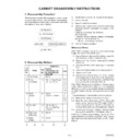
TESTMODE
TEST MODE
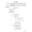
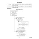
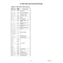
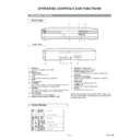
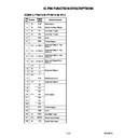
Test Mode Initial Display (Fig.T-1)
Displaying F/E Ver.
Displaying B/E Ver.
Displaying AV Decoder Ver.
Displaying DSP Ver.
Displaying VFD "B/E Ver."
< Press 1 button on the remote control unit. >
< Press 1 button on the remote control unit. >
< Press 2 button on the remote control unit. >
< Press 3 button on the remote control unit. >
< Press RETURN button on
the remote control unit. >
< Press RETURN button on
the remote control unit. >
Returning to Test Mode Initial Display
Returning to Test Mode Initial Display
All VFD ON/OFF
Menu Display (Fig. T-2)
Cearing FLASH MEMORY (Fig. T-3)
All VFD ON
All VFD OFF
Displaying VFD "TEST1"
Displaying VFD "TEST3"
Test Mode
ROM Renewal Mode
A power source is put, and [1], [2], [3], [4], and [ON SCREEN] buttons on the remote
control unit are pushed in that order while the tray is opening or after the “NO DISC”
display at the same time.
control unit are pushed in that order while the tray is opening or after the “NO DISC”
display at the same time.
A power source is put, and [9], [8], [7], [6], and [DIRECT SKIP] buttons on the remote
control unit are pushed in that order while the tray is opening or after the “NO DISC”
display at the same time.
control unit are pushed in that order while the tray is opening or after the “NO DISC”
display at the same time.
[TEST MODE]
Test Mode Flow Chart
1-7-2
TESTMODE
1. TEST1 - VFD
2. TEST2 - REPEAT PLAY
3. TEST3 - EEPROM CLEAR
4. TEST4 - MEASUREMENT SERVO
2. TEST2 - REPEAT PLAY
3. TEST3 - EEPROM CLEAR
4. TEST4 - MEASUREMENT SERVO
FE
.
BE
.
AVD
.
DSP
.
RETURN:
RETURN
EXIT:
POWER
FE
.
BE
.
AVD
.
DSP
.
RETURN:
EXIT:
RETURN
POWER
TEST1 - VFD
1. ON
2. OFF
1. ON
2. OFF
VFD STATUS [ --- ]
FE
.
BE
.
AVD
.
DSP
.
RETURN:
EXIT:
RETURN
POWER
TEST3 - FLASH MEMORY CLEAR
FLASH MEMORY CLEAR : OK
Fig. T-1: Test Mode Initial Display
Fig. T-2: All VFD ON/OFF Menu Display
Fig. T-3: Clearing FLASH MEMORY Display
1-7-3
TESTMODE
[ROM RENEWAL MODE]
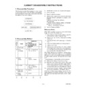
1. Turn the power on and remove the disc on the tray.
2. To put the DVD player into version up mode, press
[9], [8], [7], [6], and [DIRECT SKIP] buttons on the
remote control unit in that order. The tray will open
automatically.
remote control unit in that order. The tray will open
automatically.
Fig. a appears on the screen and Fig. b appears on
the VFD.
the VFD.
BE F/W VERSION UP MODE
PLEASE INSERT A DISC
FOR BE F/W VERSION UP.
EXIT:
POWER
Fig. a Version Up Mode Screen
Fig. b VFD in Version Up Mode
The DVD player can also enter the version up mode
with the tray open. In this case, Fig. a will be shown
on the screen while the tray is open.
with the tray open. In this case, Fig. a will be shown
on the screen while the tray is open.
3. Load the disc for version up. (For closing the tray,
only the "OPEN/CLOSE" button is available.)
4. The DVD player enters the F/W version up mode
automatically. Fig. c appears on the screen and
Fig. d appears on the VFD.
Fig. d appears on the VFD.
BE F/W VERSION UP MODE
VERSION:F1223S1E
Reading...(*2)
Fig. c Programming Mode Screen
Fig. d VFD in Programming Mode (Example)
The appearance shown in (*2) of Fig. c is described
as follows:
as follows:
Appearance
No.
State
Reading...
Sending files into the memory
Erasing...
Erasing previous version data
Programming...
1
2
3
Writing new version data
5. After programming is finished, the tray opens auto-
matically. Fig. e appears on the screen and the
checksum in (*3) of Fig. e appears on the VFD. (Fig. f)
checksum in (*3) of Fig. e appears on the VFD. (Fig. f)
BE F/W VERSION UP MODE
VERSION: ********
COMPLETED SUM:7abc(*3)
Fig. e Completed Program Mode Screen
Fig. f VFD upon Finishing the Programing Mode (Example)
At this time, no buttons are available.
6. For tray opening, plug the AC cord into the AC outlet.
7. Turn the power on by pressing the power button and
the tray will close.
1-7-4
TESTMODE
[ ERROR RATE MEASUREMENT]
1. Turn the power on, remove the disc from the tray and
close the tray.
2. To put the DVD player into test mode, press [1], [2],
[3], [4], and [ON SCREEN] buttons on the remote
control unit in that order.
control unit in that order.
Fig. a will appear on the screen and the current B/E
version will appear on the VFD. (Fig. b)
version will appear on the VFD. (Fig. b)
E56***D FE *.*** BE *.*** AVD *.*
AUD_VER :** AUD_IDE :**
DEN_CID :** FEI_REV :** VID_REV :**
AUD_VER :** AUD_IDE :**
DEN_CID :** FEI_REV :** VID_REV :**
1. TEST1-VFD
2. TEST2-REPEAT PLAY
3. TEST3-EEPROM CLEAR
4. TEST4-MEASUREMENT MODE
5. TEST5-TEST DISC
2. TEST2-REPEAT PLAY
3. TEST3-EEPROM CLEAR
4. TEST4-MEASUREMENT MODE
5. TEST5-TEST DISC
EXIT:
POWER
Fig. a Test Mode Screen
Fig. b VFD in Test Mode
3. To select No. 4 "TEST4-MEASUREMENT MODE,"
press button [4] on the remote control unit.
Fig. c will appear on the screen and Fig. d will appear
on the VFD.
on the VFD.
E56***D FE *.*** BE *.*** AVD *.*
TEST4-MEASUREMENT MODE
1. NEXT
2. LASER POWER
2. LASER POWER
EXIT:
POWER
RETURN:
RETURN
Fig. c TEST4-MEASUREMENT MODE Screen
Fig. d VFD in TEST4-MEASUREMENT MODE
4. To select No. 1 "NEXT," press button [1] on the
remote control unit.
Fig. e will appear on the screen. VFD will not change.
E56***D FE*.*** BE*.*** AVD*.*
TEST4-MEASUREMENT MODE
STATUS: * * * * * * * *
1. TRACKING SERVO ON/OFF
2. PLAY MODE
3. S-CURVE
4. AUTOMATIC ADJUSTMENT
2. PLAY MODE
3. S-CURVE
4. AUTOMATIC ADJUSTMENT
EXIT:
POWER
RETURN:
RETURN
Fig. e Next Mode Screen
5. To select No. 2 "PLAY MODE," press button [2] on
the remote control unit.
The screen will not change and the unit open the tray
automatically. VFD will not change.
automatically. VFD will not change.
6. Load the disc to measure the error rate and press
[OPEN/CLOSE] button or [PLAY] button. The unit
will close the tray automatically and fig. f will appear
on the screen.
will close the tray automatically and fig. f will appear
on the screen.
E56***D FE*.*** BE*.*** AVD*.*
TEST4-MEASUREMENT MODE
DISC:DVD / DUAL LAYER / OPPOSITE
END(or TIME): ******H(or **;**)
STATUS: * * * * * * * *
DISC:DVD / DUAL LAYER / OPPOSITE
END(or TIME): ******H(or **;**)
STATUS: * * * * * * * *
PLAY MODE
1. PLAY
2. JITTOR
3. ERROR RATE
1. PLAY
2. JITTOR
3. ERROR RATE
EXIT:
POWER
RETURN:
RETURN
Fig. f Play Mode Screen
7. To select No. 3 "ERROR RATE," press button [3] on
the remote control unit.
Fig. g will appear on the screen and Fig. d will appear
on the VFD.
on the VFD.

