Read Sharp DV-RW360H (serv.man4) Service Manual online
1-7-1
E9B30DC
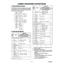
CABINET DISASSEMBLY INSTRUCTIONS
1. Disassembly Flowchart
This flowchart indicates the disassembly steps to gain
access to item(s) to be serviced. When reassembling,
follow the steps in reverse order. Bend, route, and dress
the cables as they were originally.
access to item(s) to be serviced. When reassembling,
follow the steps in reverse order. Bend, route, and dress
the cables as they were originally.
1 : Identification (location) No. of parts in the figures
2 : Name of the part
3 : Figure Number for reference
4 : Identification of parts to be removed, unhooked,
2 : Name of the part
3 : Figure Number for reference
4 : Identification of parts to be removed, unhooked,
unlocked, released, unplugged, unclamped, or de-
soldered.
P=Spring, L=Locking Tab, S=Screw,
CN=Connector,
*=Unhook, Unlock, Release, Unplug, or Desolder
e.g. 6(S-1) = six Screws (S-1),
soldered.
P=Spring, L=Locking Tab, S=Screw,
CN=Connector,
*=Unhook, Unlock, Release, Unplug, or Desolder
e.g. 6(S-1) = six Screws (S-1),
5(L-1) = five Locking Tabs (L-1)
5 : Refer to "Reference Notes."
2. Disassembly Method
↑
↑
↑
↑
↑
1
2
3
4
5
[1] Top Cover
[2] Front
Assembly
Assembly
[4] Radiation
Sheet
Sheet
[3] Front
Bracket
Bracket
[5] Jack
Bracket
Bracket
[6] Front Jack
CBA
CBA
[7] DVD
Mechanism
& DVD Main
CBA Assembly
Mechanism
& DVD Main
CBA Assembly
[9] Rear
Panel Unit
Panel Unit
[10] Power
Supply CBA
Supply CBA
[11] DC
Fan Motor
Fan Motor
[12] PCB
Holder
Holder
[13] Rear
Panel
Panel
[19] Rear
Jack CBA
Jack CBA
[14] Bracket R
[8] Dust Cover
[16] Deck
Assembly
Assembly
[21] Deck
Pedestal
Pedestal
[18] Function
CBA
CBA
[15] VCR
Chassis Unit
Chassis Unit
[17] Power
SW CBA
SW CBA
[20] Main,
AFV CBA
AFV CBA
[22] Front
Bracket R
Bracket R
ID/
LOC.
No.
PART
REMOVAL
Fig.
No.
REMOVE/*UNHOOK/
UNLOCK/RELEASE/
UNPLUG/DESOLDER
UNLOCK/RELEASE/
UNPLUG/DESOLDER
Note
[1]
Top Cover
D1
6(S-1)
---
[2]
Front
Assembly
Assembly
D2
*5(L-1), *3(L-2),
*CN1505
*CN1505
1
1-1
1-2
1-3
1-2
1-3
[3]
Front
Bracket
Bracket
D2
2(S-2), (S-3),
---
[4]
Radiation
Sheet
Sheet
D2
----------
----------
---
[5]
Jack
Bracket
Bracket
D3
2(S-4)
---
[6]
Front Jack
CBA
CBA
D3
Jack Earth Plate
---
[7]
DVD
Mechanism
& DVD
Main CBA
Assembly
Mechanism
& DVD
Main CBA
Assembly
D4
2(S-5A), 2(S-5B),
*CN101, *CN701
*CN101, *CN701
---
[8]
Dust Cover
D4
---
[10]
Power
Supply
CBA
Supply
CBA
D6
4(S-9)
---
[11]
DC Fan
Motor
Motor
D6
2(S-10)
---
[12]
PCB
Holder
Holder
D6
3(S-11), Earth Plate
---
[13] Rear Panel
D6
----------
---
[14] Bracket R
D7
2(S-12)
---
[15]
VCR
Chassis
Unit
Chassis
Unit
D7
5(S-13), 3(S-14),
2(S-15), (S-16),
(S-17), (S-18)
2(S-15), (S-16),
(S-17), (S-18)
---
[16]
Deck
Assembly
Assembly
D8
(S-19), (S-20),
Desolder
Desolder
2
3
3
[17]
Power SW
CBA
CBA
D8
Desolder
---
[18]
Function
CBA
CBA
D8
Desolder
---
[19]
Rear Jack
CBA
CBA
D8
Desolder, Earth Plate
---
[20]
Main, AFV
CBA
CBA
D8
----------
---
[21]
Deck
Pedestal
Pedestal
D9
8(S-21)
---
[22]
Front
Bracket R
Bracket R
D9
(S-22)
---
ID/
LOC.
No.
PART
REMOVAL
Fig.
No.
REMOVE/*UNHOOK/
UNLOCK/RELEASE/
UNPLUG/DESOLDER
UNLOCK/RELEASE/
UNPLUG/DESOLDER
Note
[9]
Rear Panel
Unit
Unit
D5
3(S-6A), 2(S-6B),
3(S-7), (S-8A),
(S-8B), *CN1503,
*CN1504
3(S-7), (S-8A),
(S-8B), *CN1503,
*CN1504
---
1-7-2
E9B30DC
Reference Notes
CAUTION 1: Locking Tabs (L-1) and (L-2) are fragile. Be
careful not to break them.
careful not to break them.
1-1. Release five Locking Tabs (L-1).
1-2. Release three Locking Tabs (L-2).
1-3. Disconnect Connector (CN1609), and remove the
Front Assembly.
2. When reassembling, solder wire jumpers as shown
in Fig. D8.
3. Before installing the Deck Assembly, be sure to
place the pin of LD-SW on Main CBA as shown in
Fig. D8. Then, install the Deck Assembly while
aligning the hole of Cam Gear with the pin of LD-SW,
the shaft of Cam Gear with the hole of LD-SW as
shown in Fig. D8.
Fig. D8. Then, install the Deck Assembly while
aligning the hole of Cam Gear with the pin of LD-SW,
the shaft of Cam Gear with the hole of LD-SW as
shown in Fig. D8.
(S-1)
(S-1)
(S-1)
[1] Top Cover
Fig. D1
(L-1)
(S-2)
(S-2)
(S-3)
(L-2)
(L-1)
(L-1)
[2] Front
Assembly
Assembly
[3] Front
Bracket
Bracket
[4] Radiation Sheet
CN1505
Fig. D2
Fig. D3
(S-4)
Jack Earth Plate
[5] Jack Bracket
[6] Front
Jack CBA
Jack CBA
Fig. D4
(S-5B)
(S-5A)
(S-5A)
[7] DVD
Mechanism
&
DVD Main
CBA
Assembly
Mechanism
&
DVD Main
CBA
Assembly
[8] Dust
Cover
Cover
CN101
CN701
1-7-3
E9B30DC
Fig. D5
(S-6A)
(S-7)
(S-7)
(S-7)
(S-8B)
CN1503
CN1504
(S-8A)
[9] Rear
Panel Unit
Panel Unit
(S-6B)
Fig. D6
(S-11)
(S-11)
(S-9)
(S-9)
(S-9)
(S-10)
[13] Rear Panel
[10] Power
Supply CBA
Supply CBA
[12] PCB
Holder
Holder
[11] DC Fan Motor
Earth
Plate
Plate
Fig. D7
(S-13)
(S-13)
(S-13)
(S-15)
(S-17)
(S-18)
(S-14)
(S-14)
(S-14)
(S-15)
(S-16)
(S-12)
[14] Bracket R
[15] VCR
Chassis
Unit
Chassis
Unit
1-7-4
E9B30DC
[20] Main
CBA
CBA
[16] Deck
Assembly
Assembly
[17] Power
SW CBA
SW CBA
[20] AFV CBA
[18] Function CBA
FE Head
Cylinder
Assembly
Assembly
ACE Head
Assembly
Assembly
Desolder
Lead with
blue stripe
blue stripe
[20] Main CBA
SW507
LD-SW
LD-SW
From
FE Head
FE Head
BOTTOM VIEW
Lead connections of Deck Assembly and Main CBA
Desolder
From
Capstan
Motor
Assembly
Capstan
Motor
Assembly
Printing side
Desolder
From
Cylinder
Assembly
Cylinder
Assembly
From
ACE Head
Assembly
ACE Head
Assembly
Lead with
blue stripe
blue stripe
Lead with
blue stripe
blue stripe
Desolder
Lead with
gray stripe
gray stripe
(S-19)
(S-20)
Desolder
Lead
with
blue
stripe
with
blue
stripe
Fig. D8
LD-SW
Pin
Hole
Hole
Shaft
Cam Gear
[20] Main CBA
[16] Deck Assembly
Pin
Desolder from bottom
[19] Rear
Jack CBA
Jack CBA
Earth Plate

