Read Sharp DV-NC70H (serv.man5) Service Manual online
49
DV-NC65H/S
DV-NC70H
DV-NC70H
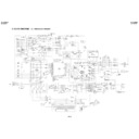
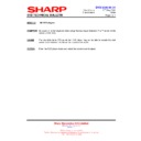
Loading motor turns in reverse
direction and master cam
clockwise.
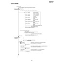
CASSETTE INSERTION STOP
Cassette
inserting
Full-
loading
YES
YES
YES
NO
NO
Loading motor starts in forward
direction and master cam counter
clockwise.
Does mechanism position switch.
come off within 2.5 sec.?
Are start/end sensors at low level
before cassette insertion ?
Insert cassette.
Drum motor starts.
Tape loading.
Pinch roller comes into contact.
Mode switch is at PB position.
Loading motor stops.
NO
Unloading
Is drum FG pulse outputted ?
End
End
Cassette is ejected and loading
motor stops.
Start sensor close.
(Cassette is judged
caught halfway.)
(Cassette LED or some other part
is judged defective.)
10.
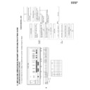
MECHANISM OPERA
TION FLO
WCHAR
T AND
TR
OUBLESHOO
TING GUIDE
MECHANISM OPERATION FLOWCHART
* This flowchart describes the outline of the mechanism
’s operation, but does not give its details.
S Sensor
Open
Close
0
1
1
1
1
0
1
1
0
1
1
1
0
0
0
0
0
0
CS/EJ
ULD
PU1
PU2
VSR
PB
SLOW
FF
STOP
Code 1
Code 2
S Sensor
Code 2
Code 1
Mecha Mode
1
0
1
1
1
1
1
1
1
1
1
0
1
0
1
0
0
0
1
0
1
0
0
0
1
0
0
0
0
0
1
0
0
0
1
0
1
0
0
0
1
0
EJ
UL
PU
PU2
VSR
PB
SLW
FF
STP
0
1
1
0
1
1
0
0
0
0
0
1
0
0
1 or 0
0°
60
120
180
200
300
360
ANGLE
CODE NO.
2
1
Code Table
0°
6.5
°
7.0
°
51.5
°
60.5
°
96.0
°
132.6
°
172.0
°
191.0
°
216.0
°
228.5
°
239.5
°
248.5
°
266.0
°
291.5
°
299.5
°
312.8
°
50
DV-NC65H/S
DV-NC70H
DV-NC70H
STOP REC/PLAY
PLAY STILL
PLAY VSR
VSR PLAY
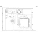
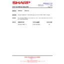
Capstan motor turns
counterclockwise.
Is take-up reel sensor signal
outputted ?
End
Press REC/PLAY key.
Picture appears.
Unloading
Set capstan motor to search
speed.
End
Press FF key.
PLAY VSF
REC/PLAY STOP
Capstan motor turns in
reverse direction.
Loading motor turns in
forward direction and master
cam counterclockwise.
Slow brake comes into
contact with capstan motor.
Slow brake
pressing
Mode switch is at STILL
position.
End
Capstan motor stops.
Press STOP key.
Loading motor stops.
End
Stop capstan motor.
NO
YES
Press STILL key.
Pinch
roller
releasing
Idler
swinging
Pinch
roller
pressing
Loading motor turns reverse
direction and master cam
clockwise.
Turn capstan motor in
reverse direction.
Turn loading motor forward
direction.
Mode switch is at VSR
position.
Set capstan motor to search
speed.
Is take-up reel sensor signal
outputted ?
Press REW key.
Release pinch roller.
Mode switch is at PU2 position.
Mode switch is at PU1 position.
Stop loading motor.
Press pinch roller.
Loading motor turns reverse
direction
Release the supply main
brake.
Stop loading motor.
End
Unloading
Mode switch is at PB position.
End
Press PLAY Key.
Loading motor turns forward
direction and master cam
counterclockwise.
Capstan motor turns
counterclockwise. PB speed.
NO
YES
51
DV-NC65H/S
DV-NC70H
DV-NC70H
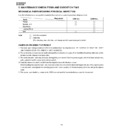
11.
TR
OUBLESHOO
TING
(VCR)
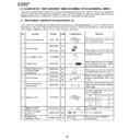
FLOW CHART NO.1
NO
YES
NO
YES
NO
YES
NO
YES
NO
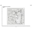
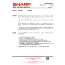
Are PC 40V, AT 27V, PC 13V, PC 5V lines
normal?
Is the fuse good?
Is the normal state restored when once unplugged
power cord is plugged again after several seconds?
Is "H" level applied at pin(1) of IC701?
The fuse blows out even when it is
replaced with new one.
See FLOW CHART NO.2 <Fuse blown out.>.
Check for leak or short-circuiting of primary circuit
part. (L901, D901~904, T901, Q901~902, etc.)
Check each rectifier circuits and short-circuit of
secondary circuit.
Check the power failure circuit. (Q706)
Are AT 5V voltage line normal?
No power
FLOW CHART NO.2
Check for leak or short-circuiting of primary
circuit part. (L901, D901~904, T901, C904, R907,
Q901~902, etc.)
Check for short-circuiting of rectifying diode and
circuit in each rectifying circuit of secondary circuit.
(D921~924, D926, D929)
Case (2)
Case (1)
Fuse blown out.
FLOW CHART NO.3
Is the voltage of AT 5V normal?
NO
YES
NO
Is 1~1.5V supplied to pins(3), (4) of IC901.
Check AT 5V rectifying circuit and secondary side.
Check PC 12V, R932.
NO
YES
YES
Are the pins(1) and (2) of IC901 turned on.
Check Q904, D913, D914 and R919.
Check the photo coupler (IC901).
Power cannot turn on from power off mode.
FLOW CHART NO.4
Is the position of mode SW (S704) and mecha
OK?
NO
YES
NO
YES
Is the pin(43) of IC701 changed from "H" to "L"
level?
Adjust the master cam.
Check VCR power line : PC 5V, PC 13V
Check DVD power line : 5V, 1.8V, 3.3V, 8V
Check serial data between video and DVD.
Turn off after power on.
FLOW CHART NO.5
Check for short-circuiting of circuit and rectifying diode of each rectifying circuit of secondary circuit
and check for failure of shunt regulator circuit. (D921~924, IC903, C927, C928)
When buzz is heard from the vicinity of power circuit.
FLOW CHART NO.6
Is the supply voltage of 5V fed up to pin(37) of IC8002?
Check STBY 5V line.
Is the supply voltage of 3.4V, 1.7V fed up to pin(38)
and pin(39) of IC8002?
Check pin(38) and pin(39) of IC8002.
Is it possible to confirm signals LCD RESET, LCD
CS, LCD DATA, LCD CLK on pins(36), (42), (43)
and (44) of IC8002?
Check signal line between IC701 and IC8002.
Is there OSC signal from pin(41) of IC8002?
Check pin(41) of IC8002.
Are common and segment signal from IC8002
supplied to LCD8002?
Replace IC8002.
Check that the fluorescent indication tube is free
from damages such as crack.
NO
NO
NO
NO
NO
YES
YES
YES
YES
YES
The VCR flourescent display tube fails light up.
52
DV-NC65H/S
DV-NC70H
DV-NC70H
FLOW CHART NO.7
Does the key switch make good contact, when the
cassette tape is inserted?
Check switch contact.
Is there the function control voltage inputted at the
pins(88) and (89) of IC701?
NO
YES
Check or replace the peripheral circuit of IC701.
YES
Key-in input is not received.
FLOW CHART NO.8
Operation is possible from the VCR, but no
operation is possible from the infrared remote
control.
Is the supply voltage of 5V fed up to pin(3) terminal
of remote control receiver?
Check AT 5V lines.
Is "L" pulse sent out from pin(1) terminal of receiver
when the infrared remote control is activated?
Replace the remote control receiver or replace the
remote control transmitter if necessary.
Is "L" pulse inputted to pin(4) of IC701?
Check line between remote control receiver thru
to pin(4) of IC701.
Replace IC701.
NO
NO
NO
YES
YES
YES
YES
No operation is possible from the infrared remote control.
FLOW CHART NO.9
Are start sensor shutter go to open when the
cassette tape is inserted?
Check start sensor shutter.
NO
YES
Does pin(87) of IC701 change from "H" to "L" level
when the cassette tape is inserted?.
Check between start sensor and pin(87) of IC701.
NO
YES
Does pin(10) of AC connector become to "H" level
(4.7V) when the cassette tape is inserted?
Check between pin(92) of IC701 and pin(10) of
AC connector.
NO
YES
Is the specified voltage (about 10V) applied at the
loading motor terminal when the cassette tape is
inserted?
Replace capstan motor unit.
NO
YES
Replace loading motor.
A cassette tape is not take in.
FLOW CHART NO.10
Does the start sensor pulse at pin(87) of IC701
change from "L" to "H" level when the cassette
tape is loaded?
Check line start sensor and all the way up thru to
pin(87) of IC701.
Does the end sensor pulse at pin(86) of IC701
change from "L" to "H" level when the cassette
tape is loaded?
Check line end sensor and all the way up thru to
pin(86) of IC701.
Does the master cam mode shifter operate
normally when the cassette tape is loaded?
Check cam switch (A), (B) and all the way
up thru to pins(94), (93) of IC701.
Replace IC701.
NO
NO
NO
YES
YES
YES
A cassette tape is taken in, but ejected at once.
FLOW CHART NO.11
Does the capstan motor start when the EJECT
button is pressed?
See FLOW CHART NO.13.
<The capstan motor fails to run.>
Does the take-up reel disk turn when the capstan
motor is running?
Check reel disk and reel drive unit.
Are pulses applied at pin(2) of IC701 when the
take-up reel disk is turning?
Check take-up reel sensor and all the
way up thru to pin(2) of IC701.
Replace cassette cam, gear, etc.
NO
NO
NO
YES
YES
YES
Is a "H" level (about 4.7V) applied at pin(10) of AC
connector when a reel pulse has been inputted?
Check pin(92) of IC701.
NO
YES
YES
Is the specified voltage applied at the loading
motor terminal?
Change the capstan motor unit.
NO
Does the loading motor run?
Replace loading motor.
NO
YES
The cassette tape fails to eject.
FLOW CHART NO.12
Does power control(H) signal at pin(96) of IC701
change from "L" to "H" level?
Check IC701.
Does the base of Q1905 change from about 5V
to 4.5V?
Check the pin(96) of IC701 and all the way up thru
to Q1905.
Is 5V sent out of the emitter of Q1905?
Check Q1905 and the AT 5V line.
NO
NO
NO
YES
YES
No power is turned on.

