Read Sharp DV-NC65H (serv.man26) User Guide / Operation Manual online
19
www.sharp.co.uk/support
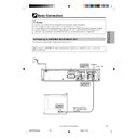
Basic Connection
Caution:
• Be sure to turn off the Unit and equipment to be connected before connecting.
• Read through the operation manual for the equipment to be connected.
• Be sure that the colours of the jacks and plugs match up when using a VIDEO/AUDIO lead (commerially available).
• Be sure to keep the Unit connection leads separate from the TV aerial lead when you install the Unit,
because it may cause electrical interference when you are watching television programmes.
Connecting to ANTENNA IN/ANTENNA OUT
The connection method differs depending on the type of TV.
The signal from ANTENNA OUT will only be the Television Signal. A scart lead MUST be used to view the units’
playback signal.
playback signal.
LINE 2
LINE 1 (TV)
S-VIDEO
OUTPUT
SELECTOR
RGB
VIDEO
S-VIDEO
AUDIO
VCR/DVD OUT
R
L
AUDIO
VIDEO
ANTENNA
IN
OUT
DVD OUT
R
L
AUDIO
DIGITAL
TV
To ANTENNA
OUT jack
OUT jack
To ANTENNA
IN jack
IN jack
To antenna
input jack
input jack
Round coaxial cable
(RF connection cable)
(supplied)
(RF connection cable)
(supplied)
Antenna
Aerial cable
CONNECTION AND
INITIAL SETTINGS
DVNC65H019_024.pm6
30/8/02, 11:14 am
19
20
www.sharp.co.uk/support
Connecting a TV with LINE 1 (TV) Output and LINE 2 Input SCARTS
Use the SCART leads (one SCART lead: supplied) to connect the Unit to your TV and VCR or
DECORDER.
DECORDER.
LINE 2
LINE 1 (TV)
S-VIDEO
OUTPUT
SELECTOR
RGB
VIDEO
S-VIDEO
AUDIO
VCR/DVD OUT
R
L
AUDIO
VIDEO
ANTENNA
IN
OUT
DVD OUT
R
L
AUDIO
DIGITAL
TV
This Unit
To LINE 2
SCART
SCART
To LINE 1 (TV)
SCART
SCART
To SCART
input
input
VCR/DVD OUT jacks can be used instead of
LINE 1(TV), depending on your TV.
LINE 1(TV), depending on your TV.
Change the position according to
the signal type (VIDEO/S-VIDEO/
RGB) that is output to TV during
DVD playback.
the signal type (VIDEO/S-VIDEO/
RGB) that is output to TV during
DVD playback.
To SCART
output
output
VCR or DECORDER
SCART OUTPUT
The factory default setting for the OUTPUT SELECTOR is “VIDEO”. If your TV supports the higher quality
modes S-VIDEO or RGB via the SCART, then please set the selector for your preference.
modes S-VIDEO or RGB via the SCART, then please set the selector for your preference.
Required leads
SCART lead (the other SCART
lead: commercially available)
lead: commercially available)
SCART lead (one SCART lead:
supplied)
supplied)
: Signal flow
Basic Connection
DVNC65H019_024.pm6
30/8/02, 11:14 am
20
21
www.sharp.co.uk/support
Basic Connection
• You will not be able to hear all of the sound being output by the Unit if you use the VIDEO/AUDIO lead
shown above to a monaural TV that has only one AUDIO input jack.
• Be sure that the colours of the jacks and plugs match up when connecting the lead.
• Connect the Unit directly to the TV. If you attempt to view video on a TV connected via a VCR, the copy protection
function will scramble the picture.
• If you want to listen to the audio through audio equipment, connect only VIDEO lead to the TV.
Connecting a TV Equipped with VIDEO/AUDIO Input Jacks
LINE 2
LINE 1 (TV)
S-VIDEO
OUTPUT
SELECTOR
RGB
VIDEO
S-VIDEO
AUDIO
VCR/DVD OUT
R
L
AUDIO
VIDEO
ANTENNA
IN
OUT
DVD OUT
R
L
AUDIO
DIGITAL
(White)
(Red)
(Yellow)
Yellow
White (L)
Red (R)
Yellow
White (L)
Red (R)
Required leads
VIDEO/AUDIO lead
(commercially available)
VIDEO/AUDIO lead
(commercially available)
(commercially available)
TV (with external input jacks)
This Unit
VIDEO
IN
AUDIO
IN
L
R
(White) (Red)
(Yellow)
To VIDEO/AUDIO
OUT jacks
OUT jacks
To VIDEO/AUDIO
input jacks
input jacks
Jack and Plug Colours
Video : Yellow
Audio Left : White
Audio Right : Red
Audio Left : White
Audio Right : Red
DVNC65H019_024.pm6
30/8/02, 11:14 am
21
22
www.sharp.co.uk/support
DVD Audio Connections
Connecting a TV Equipped with S-VIDEO Input Jacks
When you want to achieve a better video image by connecting a TV equipped with an S-VIDEO input connector
to the Unit, you should use an S-VIDEO lead (commercially available) to connect the TV to the Unit.
to the Unit, you should use an S-VIDEO lead (commercially available) to connect the TV to the Unit.
Please note, if the Output Selector Switch is set to RGB, no signal will be output from the S-VIDEO
socket.
socket.
Connecting to Audio Equipment
Connecting the Unit to audio equipment provides normal stereo sound plus powerful stereo sound enhanced
by Dolby Digital (5.1 channel), DTS, and MPEG Audio.
by Dolby Digital (5.1 channel), DTS, and MPEG Audio.
Playing 2 channel audio
■ Analogue Connection
LINE 2
LINE 1 (TV)
S-VIDEO
OUTPUT
SELECTOR
RGB
VIDEO
S-VIDEO
AUDIO
VCR/DVD OUT
R
L
AUDIO
VIDEO
ANTENNA
IN
OUT
DVD OUT
R
L
AUDIO
DIGITAL
This Unit
Required lead
VIDEO/AUDIO lead (commercially available)
White (L)
Red (R)
White (L)
Red (R)
S-VIDEO lead (commercially available)
To AUDIO
OUT jacks
OUT jacks
VIDEO/AUDIO lead
(commercially available)
(commercially available)
TV (with external input jacks)
S-VIDEO lead
(commercially available)
(commercially available)
Amplifier of stereo system, etc.
INPUT
S-VIDEO
To S-VIDEO
input jack
input jack
To amplifier
audio input jacks
audio input jacks
To S-VIDEO
OUT jack
OUT jack
Jack and Plug Colours
Audio Left: White
Audio Right: Red
Audio Right: Red
(White)
(Red)
(White)
(Red)
If the Unit is set to OPERATE ON, the DVD signals will be output from the DVD OUT jacks at all times.
(The DVD signals will be output from the DVD OUT jacks also when using the VCR.)
DVNC65H019_024.pm6
30/8/02, 11:14 am
22

