Read Sharp DV-NC65H (serv.man14) Service Manual online
43
DV-NC65H/S
DV-NC70H
DV-NC70H
10000000
~~~~~~~~
The preparation date
display of the program
10000001 00005502
Model number display
10000002
~~~~~~~~
The version display of
the program
10000003 00000002
Region number
display
10000004
~~~~~~~~ ~
Micro-code version
display
10000005
~~~~~~~~ ~~~~~~~~ Servo program version
display
10000006
~~~~~~~~
Source code version
display
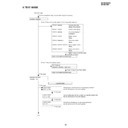
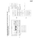
Return to the initial testmode image.
<Press "1" Key on the remote control or "Stop" Key on the main unit.>
Return to the initial testmode image.
"Playback" Key of the remote control
is pushed for 7 times.
is pushed for 7 times.
To (1)
All FIP light up
40000000 00000000 (OSD only)
<Press "4" Key of the remote control>
Press "4" Key of the remote control.
"NO DISC" state
"F0" Key input (Press "Play" Key and "Stop" Key for 5 seconds.)
F0000000 00000000
LASER TEST
DVD LD ON
LASER TEST
CD LD ON
"1" Key input
"3" Key input
"1" Key input
"1" Key input
"1" Key input
The tray opens, the DVD laser is lit, spinning is performed
and the sled moves to the outer periphery.
The DVD laser goes out, the CD laser is lit, spinning is performed
and the sled moves to the outer periphery.
LASER TEST
LD OFF
The DVD and CD laser go out, spinning is performed
and the sled moves to the outer periphery.
Laser test mode
10000006 00000000
DYNAMIC TEST
9. TEST MODE
44
DV-NC65H/S
DV-NC70H
DV-NC70H
STEP TEST
FOCUS ON
ASMAX
~~~~
ENVPP
~~~~
FEPP
~~~~
"Playback" Key input
"Playback" Key input
"Playback" Key input
Load a disc after the tray is opened.
Track on
Focus on
STEP TEST
TRACKING ON
ASMAX
~~~~
ENVPP
~~~~
FEPP
~~~~
ASAGC
~~~~
FEAGC
~~~~
FBAL0
~~~~
FBAL1
~~~~
TBAL0
~~~~
TBAL1
~~~~
"Playback" Key input
Focus balance adjustment
STEP TEST
FBAL STUDY
ASMAX
~~~~
ENVPP
~~~~
FEPP
~~~~
ASAGC
~~~~
FEAGC
~~~~
FBAL0
~~~~
FBAL1
~~~~
TBAL0
~~~~
TBAL1
~~~~
"Playback" Key input
Focus gain · track gain adjustment
STEP TEST
GAIN STUDY
ASMAX
~~~~
ENVPP
~~~~
FEPP
~~~~
ASAGC
~~~~
FEAGC
~~~~
FBAL0
~~~~
FBAL1
~~~~
TBAL0
~~~~
TBAL1
~~~~
FCGA0
~~~~
FCGA1
~~~~
TKGA0
~~~~
TKGA1
~~~~
* In case of 2-layer DVD, adjust the focus on, track on, focus balance adjustment
and focus gain · track gain adjustment.
and focus gain · track gain adjustment.
STEP TEST
DVD ID
~~~~~~~~
ASMAX
~~~~
ENVPP
~~~~
FEPP
~~~~
ASAGC
~~~~
FEAGC
~~~~
FBAL0
~~~~
FBAL1
~~~~
TBAL0
~~~~
TBAL1
~~~~
FCGA0
~~~~
FCGA1
~~~~
TKGA0
~~~~
TKGA1
~~~~
STEP TEST
TRAY OPEN
"2" Key input
To (2)
*(DVD operation)
STEP TEST
CD NO
~~
TIME
~~~~~~
ASMAX
~~~~
ENVPP
~~~~
FEPP
~~~~
ASAGC
~~~~
FEAGC
~~~~
FBAL0
~~~~
FBAL1
~~~~
TBAL0
~~~~
TBAL1
~~~~
FCGA0
~~~~
FCGA1
~~~~
TKGA0
~~~~
TKGA1
~~~~
(CD operation)
From (1)
Following playback state
Following playback state
Step execution mode
45
DV-NC65H/S
DV-NC70H
DV-NC70H
From (2)
SPIN OFFSET ADJUST
"DVD Menu" Key input
The tray opens.
SPIN OFFSET ADJUST
ADJUST COMPLETE
SPIN
~~~~
Spin offset adjustment mode
(Offset adjustment of the spindle is executed automatically.)
The adjustment result is indicated in the
~~~~ section.
PART CODE
Price Code
RUNTK0808GEZZ
CD
[ROM RENEWAL MODE]
1. A DVD itself and a personal computer are articulated as the right figure.
Software for the renewal is started more.
2. A power source is put with pushing DVD's own "Playback" Key and "Halt"
Key at the same time. (It keeps pushing it for 3 seconds.)
3. When "Y" is inputted in accordance with the personal computer display
and date transfer indication is shown and renewal process is started
normally when "Enter" Key is pushed.
normally when "Enter" Key is pushed.
4. When renewal is completed normally, it becomes POWER ON.
Personal Computer
(DOS)
DVD itself
Connect to the Audio (R)
terminal of "Input-1".
terminal of "Input-1".
Fixture for the ROM renewal
(RUNTK0808GEZZ)
(RUNTK0808GEZZ)
R : OK
It is displayed.
W : STR
It is displayed.
DVD
It is displayed.
46
DV-NC65H/S
DV-NC70H
DV-NC70H
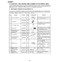
REPLACEMENT OF IC710 (E
2
PROM)
<<Servicing precautions>>
When the IC710 (E
2
PROM) has replaced, make the following reprogramming.
Depending on models, the IC710 (E
2
PROM) has been factory adjusted for its memory function.
It's therefore necessary to reprogram the memory function for the model in question.
Note that the servo circuit requires readjustments for the slow and still modes.
1. Memory function reprogramming.
a. Check the power off. (Power is standby mode.)
b. Make for moment short-circuit test point (TP801 and TP803), located at the VCR Operation PWB.
Be sure that all the VCR displays light up into the TEST mode.
c. Using the CHANNEL (+) and (-) buttons, select the right function numbers from JP0 to JP39, which appear in the VCR
LCD display, referring to the E
2
PROM map.
Press the DISPLAY button to pickup the fuctions (ON) and the CLEAR button to discard the functions (OFF).
DISPLAY and CLEAR buttons are located on the remote control unit.
* When the DISPLAY button has been pressed (ON), the memory function number starts flashing.
* When the CLEAR button has been pressed (OFF), the memory function number lights up.
d. Example: "ON" and "OFF" are taken as "1" and "0" respectedly.
The numbers JP0 to JP39 are divided into four groups and each group's setting is displayed in hexadecimal notation.
Also recording level preset number selected from the ten keys on the remote control unit which appear in the VCR LCD display,
referring to the E
2
PROM map.
2.
Memory recording preset level reprogramming.
a. Similarly to the above step 1-a and 1-d the same operate.
b. Using the CHANNEL (+) and (-) buttons, select the right function numbers continued from recording preset number as has been
JP0~JP39, which appear in the VCR LCD display, referring to the E
2
PROM map.
c. Example:
3. Finally make for a moment short-circuit test point (TP801 and TP803), both located at the VCR Operation PWB to clear the TEST
mode.
JP0
JP1
JP2
JP3
JP4
JP5
JP6
JP7
JP8
JP9 JP10 JP11 JP12 JP13 JP14 JP15 JP16 JP17 JP18 JP19 JP20 JP21 JP22 JP23 JP24 JP25 JP26 JP27
0
0
1
0
0
1
0
0
1
1
0
1
1
1
0
1
1
1
1
0
0
1
1
1
1
0
1
0
↓
↓
↓
↓
↓
↓
↓
4
2
B
B
7
E
5
JP28 JP29 JP30 JP31 JP32 JP33 JP34 JP35 JP36 JP37 JP38 JP39
0
1
0
0
0
1
0
0
1
1
0
0
↓
↓
↓
2
2
3
Out lights
SP
p
*
*
LP
p
*
*
SP
n
*
*
EP
n
*
*
↑
↑
↑
↑
↑
↑
↑
↑
Blank
Selection from the
Selection from the
Selection from the
Selection from the
ten keys.
ten keys.
ten keys.
ten keys.
(from "0" to "7")
(from "0" to "7").
(from "0" to "7")
(from "0" to "7")
System
p : PAL
↓
n : NTSC
Tape speed
→ SP, LP or EP
n *
*
↑
↑
Chrominance preset number. (from "0" to "7")
Luminance preset number. (from "0" to "7")

