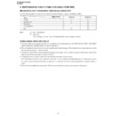
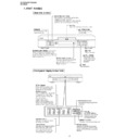
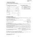
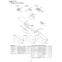
Read Sharp DV-720H (serv.man22) Service Manual online
7
DV-720S/DV-720S(K)
DV-720H
DV-720H
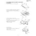
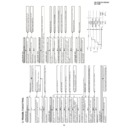
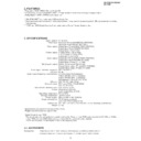
6. DISASSEMBLY AND REPLACEMENT OF MAIN PARTS
6-1. DISASSEMBLY
1. Remove the five screws (A), and remove the top cabinet.
SHARP
Top Cabinet
(A)x2
(A)x1
(A)x2
2. Remove the five screws (B), and at two hooks on both sides and
at three places on the bottom, and remove the front panel.
3. Remove the four screws (C), and a connector and remove the
mechanism.
g
e
Mechanism
Front Panel
(B)x1
(B)x1
(B)x1
(B)x2
(C)x4
f
4. Remove the two screws (D) of the main PWB.
Two hooks of the spacer and a connector are removed, and main
PWB is removed.
5. Remove the four screws (E) fixing the terminal PWB, and fixing the
terminal from screws (F) the back is removed.
Note: Six screws (F) varies in the model.
Remove the terminal PWB.
6. Remove the spacer.
Remove the front spacer.
Two back foots (G) can be removed by pushing middle pin in the
direction of the arrow.
Remove the two screws (H) of the front foots.
i
j
h
h
j
i
Main PWB
Terminal PWB
(E)x4
(F)x6
(D)x2
(G)x2
(H)x2
DV-720S/DV-720S(K)
DV-720H
DV-720H
8
6-2. REPLACEMENT OF MAIN PARTS
<Take out disk>
1. Remove the top cabinet.
2. It is in such cases as the thin driver, and it is pushed in slowly, and a tray is drawn in the arrow direction the slide rack on the
2. It is in such cases as the thin driver, and it is pushed in slowly, and a tray is drawn in the arrow direction the slide rack on the
left of the base chassis.
3. Take out disk.
Front Side
<Disassembling and assembling the mechanism chassis>
1. Remove the four base chassis mounting screws.
2. Remove the loading motor lead wire and sled motor lead wire from the main PWB.
3. To protect the pickup against breakage by static electricity, turn the base chassis over with the pickup FFC connected and short-
2. Remove the loading motor lead wire and sled motor lead wire from the main PWB.
3. To protect the pickup against breakage by static electricity, turn the base chassis over with the pickup FFC connected and short-
circuit (solder) the short land of the superposition PWB.
4. Remove the pickup FFC from the main PWB.
5. Remove the pickup FFC from the superposition PWB.
6. Remove the traverse mounting screws to remove the traverse chassis ass'y.
Note: After assembly and wiring, remove the solder joint of the short land. If short-circuited, a disk is not played back.
5. Remove the pickup FFC from the superposition PWB.
6. Remove the traverse mounting screws to remove the traverse chassis ass'y.
Note: After assembly and wiring, remove the solder joint of the short land. If short-circuited, a disk is not played back.
1. Remove the pickup FPC and loading relay FFC A from the main PWB.
Note: Fit the conductive rubber cap to the front end of pickup FPC (short-circuit).
2. Remove the solder joint of loading relay PWB at drive unit rear side.
1
Sled motor lead wire (Yellow·Orange)
2
IN SW lead wire 2 (White)
3
Spindle motor lead wire (Red·Black)
4
Loading motor lead wire (Red·Black)
5
Remove each lead wire from the claw.
3. Remove the relay PWB mounting screw B (M2.6S + 6S S tight),
and remove the relay PWB C .
Sled Motor Lead Wire
Pickup FFC
Traverse Fixing Screw
Loading Motor Lead Wire
Superposition PWB
Pickup FFC
Short Land
<Replacing the pickup and the spindle motor>
Since the pickup optical axis and turntable inclination of DVD are adjusted with higher accuracy than of CD/MD, make a replacement
as a mechanism service chassis ass'y (refer to Parts List).
as a mechanism service chassis ass'y (refer to Parts List).
Display

