Read Sharp XL-S10H (serv.man9) Service Manual online
XL-S10H
7 – 1
Audio
XL-S10H
Service Manual
XS10H
Market
E
CHAPTER 7.
OTHERS
[1] FUNCTION TABLE OF IC
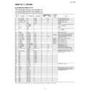
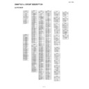
IC701 RH-iXA006SJZZ: System Microcomputer (IXA006SJ) (1/2)
IC701 RH-iXA007SJZZ: System Microcomputer (IXA007SJ) (1/2)
IC701 RH-iXA019SJZZ: System Microcomputer (IXA019SJ) (1/2)
In this unit, the terminal with asterisk mark (*) is (open) terminal which is not connected to the outside.
Pin
No.
No.
Port Name
Terminal Name
Input/Output
Terminal status
Option
resistor,
etc.
Function
Reset
Active
1
I_TU_DATA
P14
Input
L
H/L
LV23002 serial data input
2
O_TU_CLK
P15
Output
L
H/L
LV23002 serial clock output
3
O_FUNC_DATA
P16
Output
L
H/L
BD3881 CONT output
4
O_FUNC_CLK
P17
Output
L
H/L
BD3881 CONT output
5
—
RES
Input
RESET
6
—
XT1/AN10
—
Terminal connecting resonator for sub
clock f=32.768kHz
clock f=32.768kHz
7
—
XT2/AN11
—
8
GND
VSS1
—
GND
9
—
CF1
—
Terminal connecting resonator for main
clock f=8.5MHz
clock f=8.5MHz
10
—
CF2
—
11
VDD1
VDD1
—
Power supply +5.0V
12
I_HOLD
P80/AN0
Input
H
H
Power supply voltage monitoring input
13
I_VP_CHK
P81/AN1
Input
A/D Input
Abnormal voltage monitoring input
14
I_CD_LID
P82/AN2
Input
L
H/L
CD lid OPEN detection SW input
15
I_CD_DRF
P83/AN3
Input
L
H/L
CD DRF signal input
16
I_TP_STATE
P84/AN4
Input
A/D Input
DECK status monitoring input
17
I_VOL_ENC
P85/AN5
Input
A/D Input
VOL encoder input
18
I_KEY1
P86/AN6
Input
A/D Input
Main unit KEY input 1
19
I_KEY2
P87/AN7
Input
A/D Input
Main unit KEY input 2
20
I-SUFIX
P70/INT0/AN8
Input
A/D Input
Destination select input
21
I_CD_WRQ
P71/INT1/AN9
Input
L
H/L
CD WRQ signal input
22
O_POWER
P72/INT2
Output
L
H/L
Power ON/OFF output
23
I_REM
P73/INT3
Input
L
H/L
Remote control pulse signal input
24
IO_EEP_DATA
S0/PA0
Input/Output
L
H/L
EEPROM control data input/output
(Pull-down at 100k? when not used)
(Pull-down at 100k? when not used)
25
S1/PA1
26
O_EEP_CLK
S2/PA2
Output
L
H/L
EEPROM control clock output
27*
NC
S3/PA3
Output
L
L
“L” fixed output
28*
NC
S4/PA4
Output
L
L
29*
NC
S5/PA5
Output
L
L
30*
NC
S6/PA6
Output
L
L
31*
NC
S7/PA7
Output
L
L
32*
NC
S8/PB0
Output
L
L
33*
NC
S9/PB1
Output
L
L
34*
NC
S10/PB2
Output
L
L
35*
NC
S11/PB3
Output
L
L
36
S19
S12/PB4
—
LCD segment output
37
S18
S13/PB5
—
38
S17
S14/PB6
—
39
VDD2
VDD2
—
Microprocessor power supply +5.0V
40
GND
VSS2
—
Microprocessor power supply GND
41
S16
S15/PB7
—
LCD segment output
42
S15
S24/PD0
—
43
S14
S25/PD1
—
44
S13
S26/PD2
—
45
S12
S27/PD3
—
46
S11
S28/PD4
—
47
S10
S29/PD5
—
48
S09
S30/PD6
—
49
S08
S31/PD7
—
50
S07
S32/PE0
—
XL-S10H
7 – 2
IC701 RH-iXA006SJZZ: System Microcomputer (IXA006SJ) (2/2)
IC701 RH-iXA007SJZZ: System Microcomputer (IXA007SJ) (2/2)
IC701 RH-iXA019SJZZ: System Microcomputer (IXA019SJ) (2/2)
In this unit, the terminal with asterisk mark (*) is (open) terminal which is not connected to the outside.
Pin
No.
No.
Port Name
Terminal Name
Input/Output
Function
Reset
Active
51
S06
S33/PE1
—
LCD segment output
52
S05
S34/PE2
—
53
S04
S35/PE3
—
54
S03
S36/PE4
—
55
S02
S37/PE5
—
56
S01
S38/PE6
—
57
S00
S39/PE7
—
58
NC
V3/PL6
—
59
NC
V2/PL5
—
60
NC
V1/PL4
—
61
COM0
COM0/PL0
—
LCD common output
62
COM1
COM1/PL1
—
63
COM2
COM2/PL2
—
64
COM3
COM3/PL3
—
65
NC
PWM2
Output
L
L
“L” fixed output
66
GND
VSS3
—
Microprocessor power supply GND
67
VDD3
VDD3
—
Microprocessor power supply +5.0V
68*
NC
PWM3
Output
L
L
“L” fixed output
69
O_BK_LED
P00
Output
L
H/L
LCD Back Light output
70*
NC
P01
Output
L
L
“L” fixed output
71*
NC
P02
Output
L
L
72*
NC
P03
Output
L
L
73
O_AMP_ON
P04
Output
L
H/L
AMP ON output
74
O_CD_RESET
P05
Output
L
H/L
CD RESET output
75
O_CD_CE
P06
Output
L
H/L
CD serial communication chip enable out-
put
put
76
O_TU_CE
P07
Output
L
H/L
LV23002 serial communication CS output
77
O_CD_DATA
P10
Output
L
H/L
CD serial communication data output
78
I_CD_DATA
P11
Input
L
H/L
CD serial communication data input
79
O_CD_CLK
P12
Output
L
H/L
CD serial communication clock output
80
O_TU_DATA
P13
Output
L
H/L
LV23002 serial communication data output
XL-S10H
7 – 3
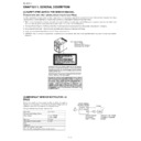
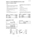
[2] LCD DISPLAY
RV-LX0008SJZZ
Z1
Z2
2
1
3
q4
9
o
k
r5
q5
7
Z4
Z3
1 2 3 4 5 6 7 8 9 10 11 12 13 14 15 16 17 18 19 20 21 22 23 24
PinNo
1
2
3
4
5
6
7
8
9
10
11
12
com1
com1
f2
a1
g1
i1
a2
m2
VOL
a3
com2
com2
e2
h1
j1
f1
b2
j2
b3
j3
com3
com3
EQ
b1
k1
e1
c2
n2
c3
p3
com4
com4
c1
d1
z1
z2
d2
AUX
d3
PinNo
13
14
15
16
17
18
19
20
21
22
23
24
com1
a4
g4
AM
PM
a5
z3
a6
REC
b7
a7
SLEEP
com2
f3
b4
j4
f4
b5
f5
r5
b6
f6
j7
f7
kHz
com3
e3
c4
k4
e4
j5
e5
q5
j6
e6
c7
e7
MHz
com4
RANDOM
d4
q4
c5
d5
MEMORY
c6
d6
ST
d7
z4
XL-S10H
7 – 4
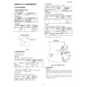
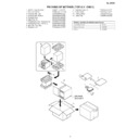
[3] WIRING OF PRIMARILY SUPPLY LEADS (FOR U.K. ONLY)
If any one of the bands shown in Fig.1 is removed for some reason, be
sure replace it to the original position and same appearance as before.
sure replace it to the original position and same appearance as before.
Figure 1
Blue
Nylon Band
LHLDW1001SJZZ
LHLDW1001SJZZ
AC Power
Supply Cord
Power
Transformer
Brown

