Read Sharp XL-MP35H (serv.man11) Service Manual online
XL-MP35H
– 8 –
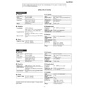
MECHANISM SECTION
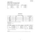
• Driving Force Check
Torque Meter
Specified Value
Play: TW-2412
Over 80 g
• Torque Check
Torque Meter
Play: TW-2111
30 to 60 g. cm
Fast forward: TW-2231
55 to 140 g.cm
Rewind: TW-2231
55 to 140 g.cm
Specified
Value
Adjusting
Point
Instrument
Connection
Test Tape
ADJUSTMENT
Specified Value
• Tape Speed
TUNER SECTION
MTT-111
Variable
3,000
±
Headphone
resistor in
90 Hz
terminal
motor.(M901)
Check Point
Instrument
Connection
Display
Frequency
87.5 MHz
87.5 MHz
3.4 V
±
1.0 V
TP301
108 MHz
108 MHz
7.8 V
±
1.0 V
TP301
• Check FM VT
Signal generator: 1 kHz, 40 kHz dev., FM modulated
Signal generator: 1 kHz, 40 kHz dev., FM modulated
Frequency
Frequency
Display
Setting/
Adjusting
Parts
Instrument
Connection
IF
450 kHz
1,602 kHz
T351
*1
AM Band
—
531 kHz
(fL): T306
*2
Coverage
1.1
±
0.1 V
AM
990 kHz
990 kHz
T302
*1
Tracking
fL: Low-range frequency
fH: High-range frequency
fH: High-range frequency
Signal generator: 400 Hz, 30%, AM modulated
• AM IF/RF
Adjusting
Parts
Instrument
Connection
Display
Frequency
98.00 MHz
98.00 MHz
VR351*1
Input: CNP301
(30 dB
µ
V)
Output: Speaker
Terminal
Terminal
• FM RF
Signal generator: 1 kHz, 75 kHz dev., FM modulated
Signal generator: 1 kHz, 75 kHz dev., FM modulated
FM Band
—
87.50 MHz
(fL): L303
*1
Coverage
3.4
±
0.1 V
FM RF
98.00 MHz
98.00 MHz
L302
*2
(10~30 dB)
Test Stage
Frequency
Frequency
Display
Setting/
Adjusting
Parts
Instrument
Connection
*1. Input: Antenna,
Output: TP301
*2. Input: Antenna,
Output: Speaker Terminal
• FM Detection
Signal generator: 10.7 MHz, FM sweep generator
Signal generator: 10.7 MHz, FM sweep generator
FM IF
10.7 MHz
98.00 MHz
T304(Turn
Input: Pin 1 of
the core of
IC301
T304 fully
counter-
clockwise).
counter-
clockwise).
Test
Stage
Frequency
Frequency
Display
Setting/
Adjusting
Parts
Instrument
Connection
• FM Mute Level
Signal generator: 1 kHz, 40 kHz dev., FM modulated
Signal generator: 1 kHz, 40 kHz dev., FM modulated
*1. Adjust so that an output signal appears.
TAPE MECHANISM
M901
Tape
Motor
Tape
Motor
Variable
resistor
in motor
resistor
in motor
IC303
IC302
CF352
R336
T306
VR351
T302
T304
L303
IC301
L302
BF301
T351
1
9
MAIN PWB
ANTENNA
SOCKET
SOCKET
FM Mute
Level
Level
AM IF
TP301
CNP301
AM
Tracking
Tracking
AM Band
Coverage fL
Coverage fL
FM Band
Coverage fL
Coverage fL
FM RF
FM IF
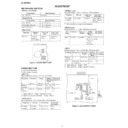
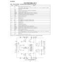
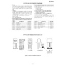
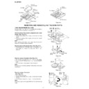
Figure 8-1 ADJUSTMENT POINT
Figure 8-2 ADJUSTMENT POINTS
*1. Input: Antenna
Output: Speaker terminal
*2. Input: Input is not connected
Output: TP301
– 9 –
XL-MP35H
TEST MODE
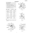
• Setting the Test Mode
Keeping the REW/REV button and BASS/TREBLE button
pressed, turn on POWER. Then, the frequency is initially set
in the memory as shown in Table. Call it with the PRESET
button to use it for adjustment and check of tuner circuit.
Keeping the REW/REV button and BASS/TREBLE button
pressed, turn on POWER. Then, the frequency is initially set
in the memory as shown in Table. Call it with the PRESET
button to use it for adjustment and check of tuner circuit.
Preset No.
FM STEREO
Preset No.
AM
1
87.50 MHz
2
108.00 MHz
3
98.00 MHz
4
90.00 MHz
5
106.00 MHz
11~25
––––
6
531 kHz
7
1,602 kHz
8
990 kHz
9
603 kHz
10
1,404 kHz
Preset No.
FM MONO
26
106.00 MHz
27
90.00 MHz
28
98.00 MHz
29
108.00 MHz
30
87.50 MHz
BAND
11-35
36
FM106.00 MHz
37
FM 90.00 MHz
38
FM
FM 98.00 MHz
39
MONO
FM108.00 MHz
40
FM 87.50 MHz
Europe 1, 2
CH
BAND
1
FM 87.50 MHz
2
FM108.00 MHz
3
FM
FM 98.00 MHz
4
STEREO
FM 90.00 MHz
5
FM106.00 MHz
Europe 1, 2
CH
BAND
6
AM 522 kHz
7
AM1620 kHz
8
AM
AM 990 kHz
9
AM 603 kHz
10
AM1404 kHz
Europe 1, 2
CH
Stations are set according to destination.
KEY1
KEY2
KEY3
TEST CONTENTS
Memory
Function
Power
Preset clear
Memory
Stop
Power
Preset set
Memory
Play
Power
Display
Memory
Preset up
Power
CD
Memory
Rec
Power
Soft reset
Bass/treble
Function
Power
Volume
Bass/treble
Stop
Power
Tuner aspm
Bass/treble
Play
Power
Timer test
Bass/treble
Rec
Power
All key
Test Mode Key Operation
• Preset clear test
• Preset set test
All test modes can be terminated by turning off the power with POWER key.
All tuner preset stations are cleared.
• Display test
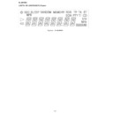
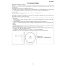
When test mode is activated, the entire display lights up. As the “PLAY” button is pressed, half of the display lights up alternately.
Display

