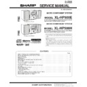
Read Sharp XL-HP500 (serv.man6) Service Manual online
XL-HP500E
XL-HP500H
– 4 –
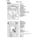
NAMES OF PARTS
■
Front panel
1. Disc Trays
2. On/Stand-by Button
3. Timer/Sleep Button
4. Clock Button
5. Tuning and Time Down Button
6. Tuning and Time Up Button
7. Timer Set Indicator
8. Headphone Socket
9. CD Eject Buttons
2. On/Stand-by Button
3. Timer/Sleep Button
4. Clock Button
5. Tuning and Time Down Button
6. Tuning and Time Up Button
7. Timer Set Indicator
8. Headphone Socket
9. CD Eject Buttons
10. CD Direct Play Buttons
11. Equaliser Mode Select Button
12. Extra Bass/Demo Mode Button
13. Volume Control
14. Cassette Compartment
15. Tape Reverse Play Button
16. CD or Tape Stop Button
17. CD Play or Repeat, Tape Forward Play Button
18. CD Track Down or Fast Reverse, Tape Fast Wind,
11. Equaliser Mode Select Button
12. Extra Bass/Demo Mode Button
13. Volume Control
14. Cassette Compartment
15. Tape Reverse Play Button
16. CD or Tape Stop Button
17. CD Play or Repeat, Tape Forward Play Button
18. CD Track Down or Fast Reverse, Tape Fast Wind,
Tuner Preset Down Button
19. CD Track Up or Fast Forward, Tape Fast Wind,
Tuner Preset Up Button
20. CD Button
21. Tape Record Pause Button
22. Video/Auxiliary Button
23. Tuner (Band) Button
24. Tape Reverse Mode Select Button
25. Memory/Set Button
26. Tape Button
21. Tape Record Pause Button
22. Video/Auxiliary Button
23. Tuner (Band) Button
24. Tape Reverse Mode Select Button
25. Memory/Set Button
26. Tape Button
3
2
1
4
5
6
7
5
6
7
8
10
9
11
13
12
14
15
17 18 19
22
20
21
23 24 25 26
16
■
Display
1. Disc Number Indicators
2. CD Play Indicator
3. Tape Reverse Mode Indicator
4. Tape Reverse Play Indicator
5. Tape Forward Play Indicator
6. FM Stereo Mode Indicator
7. FM Stereo Receiving Indicator
8. Memory Indicator
9. Extra Bass Indicator
2. CD Play Indicator
3. Tape Reverse Mode Indicator
4. Tape Reverse Play Indicator
5. Tape Forward Play Indicator
6. FM Stereo Mode Indicator
7. FM Stereo Receiving Indicator
8. Memory Indicator
9. Extra Bass Indicator
10. Timer Recording Indicator
11. Timer Play Indicator
12. CD Pause Indicator
13. CD Repeat Play Indicator
14. Tape Record Indicator
15. Sleep Indicator
11. Timer Play Indicator
12. CD Pause Indicator
13. CD Repeat Play Indicator
14. Tape Record Indicator
15. Sleep Indicator
■
Rear panel
1. Cooling Fan
2. Subwoofer Output Socket
3. AC Power Lead
4. FM 75 Ohms Aerial Socket
5. AM Loop Aerial Socket
6. Video/Auxiliary (Audio Signal) Input Sockets
7. Speaker Terminals
2. Subwoofer Output Socket
3. AC Power Lead
4. FM 75 Ohms Aerial Socket
5. AM Loop Aerial Socket
6. Video/Auxiliary (Audio Signal) Input Sockets
7. Speaker Terminals
Note:
This product is equipped with a cooling fan inside, which begins to
run at a specified volume level for better heat radiation.
This product is equipped with a cooling fan inside, which begins to
run at a specified volume level for better heat radiation.
■
Speaker system
1. Tweeter
2. Woofer
3. Bass Reflex Duct
4. Speaker Terminals
2. Woofer
3. Bass Reflex Duct
4. Speaker Terminals
3
1
2
3
4
5
6
7
4
2
1
3 4 5
6 7 8 9
10
11
11
15
14
12 13
1
2
XL-HP500E
– 5 –
XL-HP500E
XL-HP500H
XL-HP500H
■
Front panel
1. Disc Trays
2. On/Stand-by Button
3. Timer/Sleep Button
4. Clock Button
5. Tuning and Time Down Button
6. Tuning and Time Up Button
7. Timer Set Indicator
8. Headphone Socket
9. CD Eject Buttons
2. On/Stand-by Button
3. Timer/Sleep Button
4. Clock Button
5. Tuning and Time Down Button
6. Tuning and Time Up Button
7. Timer Set Indicator
8. Headphone Socket
9. CD Eject Buttons
10. CD Direct Play Buttons
11. Equaliser Mode Select Button
12. Extra Bass/Demo Mode Button
13. Volume Control
14. Cassette Compartment
15. Tape Reverse Play Button
16. CD or Tape Stop Button
17. CD Play or Repeat, Tape Forward Play Button
18. CD Track Down or Fast Reverse, Tape Fast Wind,
11. Equaliser Mode Select Button
12. Extra Bass/Demo Mode Button
13. Volume Control
14. Cassette Compartment
15. Tape Reverse Play Button
16. CD or Tape Stop Button
17. CD Play or Repeat, Tape Forward Play Button
18. CD Track Down or Fast Reverse, Tape Fast Wind,
Tuner Preset Down Button
19. CD Track Up or Fast Forward, Tape Fast Wind,
Tuner Preset Up Button
20. CD Button
21. Tape Record Pause Button
22. Video/Auxiliary Button
23. RDS Display Mode Select Button
24. Tuner (Band) Button
25. Tape Reverse Mode Select Button
26. Memory/Set Button
27. Tape Button
28. RDS ASPM (Auto Station Programme Memory) Button
29. RDS Programme Type/Traffic Information
21. Tape Record Pause Button
22. Video/Auxiliary Button
23. RDS Display Mode Select Button
24. Tuner (Band) Button
25. Tape Reverse Mode Select Button
26. Memory/Set Button
27. Tape Button
28. RDS ASPM (Auto Station Programme Memory) Button
29. RDS Programme Type/Traffic Information
Search Button
3
2
1
4
5
6
7
5
6
7
8
10
9
11
13
12
14
15
17 18 19
22
20
21
24 25 26 27 28 29
23
16
■
Display
1. Disc Number Indicators
2. CD Play Indicator
3. Tape Reverse Mode Indicator
4. Tape Reverse Play Indicator
5. Tape Forward Play Indicator
6. RDS Indicator
7. Traffic Announcement Indicator
8. Traffic Programme Indicator
9. Dynamic PTY Indicator
2. CD Play Indicator
3. Tape Reverse Mode Indicator
4. Tape Reverse Play Indicator
5. Tape Forward Play Indicator
6. RDS Indicator
7. Traffic Announcement Indicator
8. Traffic Programme Indicator
9. Dynamic PTY Indicator
10. FM Stereo Mode Indicator
11. FM Stereo Receiving Indicator
12. Memory Indicator
13. Extra Bass Indicator
14. Timer Recording Indicator
15. Timer Play Indicator
16. CD Pause Indicator
17. CD Repeat Play Indicator
18. Tape Record Indicator
19. Sleep Indicator
11. FM Stereo Receiving Indicator
12. Memory Indicator
13. Extra Bass Indicator
14. Timer Recording Indicator
15. Timer Play Indicator
16. CD Pause Indicator
17. CD Repeat Play Indicator
18. Tape Record Indicator
19. Sleep Indicator
■
Rear panel
1. Cooling Fan
2. Subwoofer Output Socket
3. AC Power Lead
4. FM 75 Ohms Aerial Socket
5. AM Loop Aerial Socket
6. Video/Auxiliary (Audio Signal) Input Sockets
7. Speaker Terminals
2. Subwoofer Output Socket
3. AC Power Lead
4. FM 75 Ohms Aerial Socket
5. AM Loop Aerial Socket
6. Video/Auxiliary (Audio Signal) Input Sockets
7. Speaker Terminals
Note:
This product is equipped with a cooling fan inside, which begins to
run at a specified volume level for better heat radiation.
This product is equipped with a cooling fan inside, which begins to
run at a specified volume level for better heat radiation.
■
Speaker system
1. Tweeter
2. Woofer
3. Bass Reflex Duct
4. Speaker Terminals
2. Woofer
3. Bass Reflex Duct
4. Speaker Terminals
1
2
3
4
5
6
7
3
4
1
2
2
1
3 4 5 6 7 8
9 10 11 12 13
14
15
15
19
18
16 17
XL-HP500E
XL-HP500H
– 6 –
■
Remote control
1. Remote Control Transmitter
2. CD Direct Play Buttons
3. CD Track Down or Fast Reverse, Tape Fast Wind,
2. CD Direct Play Buttons
3. CD Track Down or Fast Reverse, Tape Fast Wind,
Tuner Preset Down Button
4. Clock Button
5. Equaliser Mode Select Button
6. Extra Bass Button
7. On/Stand-by Button
8. CD Button
9. Tuner (Band) Button
5. Equaliser Mode Select Button
6. Extra Bass Button
7. On/Stand-by Button
8. CD Button
9. Tuner (Band) Button
10. Tape Button
11. Video/Auxiliary Button
12. CD Track Up or Fast Forward, Tape Fast Wind,
11. Video/Auxiliary Button
12. CD Track Up or Fast Forward, Tape Fast Wind,
Tuner Preset Up Button
13. Volume Up and Down Buttons
14. Disc Direct Search Buttons
15. CD Clear Button
16. CD Memory Button
17. CD Stop Button
18. CD Pause Button
19. Tape Reverse Mode Select Button
20. Tape Reverse Play Button
21. Tape Stop Button
22. CD Play or Repeat Button
23. Tape Record Pause Button
24. CD Random Button
25. Tape Forward Play Button
1
2
3
4
5
6
6
7
8
9
10
11
12
14
13
15
16
16
22
23
24
25
23
24
25
17
18
19
20
19
20
21
Buttons with " " mark in the illustration can be operated on the re-
mote control only.
mote control only.

