Read Sharp XL-HP404 (serv.man6) Service Manual online
XL-HP404E/HP404H
3 – 1
Audio
XL-HP404E/HP404H
Service Manual
XL-HP404H
Market
E
CHAPTER 3.
MECHANICAL DESCRIPTION
[1] REMOVING AND REINSTALLING THE
MAIN PARTS
MAIN PARTS
1. TAPE MECHANISM SECTION
Perform steps 1 to 9 of the disassembly method to remove the tape
mechanism.(see page 3-3,3-4)
mechanism.(see page 3-3,3-4)
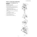
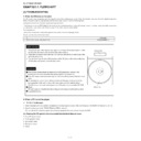
1.1. How to remove the Record/Playback Head (See Fig. 1)
1. When you remove the screws (A1) x 2 pcs and (A2) x 1 pc., the
record/playback head can be removed.
1.2. How to remove the Pinch Roller (See Fig. 2)
1. Carefully bend the pinch roller pawl in the direction of the arrow
<A>, and remove the pinch roller (B1) x 1 pc., in the direction of the
arrow <B>.
arrow <B>.
NOTE: When installing the pinch roller, pay attention to the spring
mounting position.
1.3. How to remove the Belt (See Fig. 3)
1. Remove the main belt (C1) x 1 pc., from the motor side.
2. Remove the FF/REW belt (C2) x 1 pc.
1.4. How to remove the Motor (See Fig. 4)
1. Remove the screws (D1) x 2 pcs., to remove the motor.
Figure 1
Figure 2
Figure 3
Figure 4
(A1)x2
Ø2x6mm
Ø2x6mm
(A2)x1
Ø2x9mm
Ø2x9mm
Record/Playback
Head
Head
Erase Head
Clutch Ass'y
Pinch Roller
(B1)x1
<A>
<B>
Pinch
Roller
Pawl
Pull
Main Belt
(C1)x1
FF/REW
Belt
(C2)x1
Motor
FF/REW
Clutch
Flywheel
(D1)x2
Ø2.6x5mm
Motor
Clutch Ass'y
XL-HP404E/HP404H
3 – 2
2. CD MECHANISM SECTION
Perform steps 1 to 4 and 11 to 12 of the disassembly method to
remove the CD mechanism.(see page 3-3,3-4)
remove the CD mechanism.(see page 3-3,3-4)
2.1. How to remove the Optical Pickup (See Fig. 1)
1. Remove the screws (A1) x 2 pcs and shaft (A2) x 1 pc.
2. Remove the stop washer (A3) x 1 pc and gear (A4) x 1 pc.
3. Remove the optical pickup.
NOTE: After pulling out the optical pickup connector, wrap the tip of it
with conductive aluminium foil or the like to protect the optical
pickup from the static electricity.
pickup from the static electricity.
2.2. How to remove CD Disc (See Fig. 2~5)
1. When CD is at play position, Rotate reduction gear C clock-wise as
shown in Figure 2 Until disk tray is at stalk position, then rotate fur-
ther to eject the disk tray so that CD can be removed from the tray.
ther to eject the disk tray so that CD can be removed from the tray.
2. In another case, if CD mechanism is at tray No. 1 play position and
to remove CD located in tray No. 3, the procedure is as follows:
If the gear up down board is located at tray No. 1 position, then
rotate gear clock-wise until it is at stalk position. Rotate reduction
gear D (Figure 3) to move the CD mechanism to tray No. 3 position.
This is confirmed by checking the gear up down board position by
the marking as indicated on the main chassis as shown in Figure 4.
rotate gear clock-wise until it is at stalk position. Rotate reduction
gear D (Figure 3) to move the CD mechanism to tray No. 3 position.
This is confirmed by checking the gear up down board position by
the marking as indicated on the main chassis as shown in Figure 4.
Figure 5
CD Disc
CD At play position.
Disc Tray
Guide Tray
CD Disc
CD At stalk position.
Figure 1
Figure 4
(A1) x2
ø2.6 x5mm
CD
Mechanism
Stop Washer
(A3) x1
Optical Pickup
Gear
(A4) x1
Shaft
(A2) x1
Reduction gear D
Figure 3
Up
Down
Reduction gear C
Front
Figure 2
Rear
Mark 1
(DISC 1)
(DISC 2)
(DISC 3)
(DISC 4)
(DISC 5)
Gear up down board
Mark 3
Mark 5
Mark 2
Mark 4
XL-HP404E/HP404H
3 – 3
[2] DISASSEMBLY
Note 1:
After removing the connector for the optical pickup from the connector,
wrap the conductive aluminium foil around the front end of the connec-
tor so as to protect the optical pickup from electrostatic damage.
wrap the conductive aluminium foil around the front end of the connec-
tor so as to protect the optical pickup from electrostatic damage.
Caution on Disassembly
Follow the below-mentioned notes when disassembling the unit and
reassembling it, to keep it safe and ensure excellent performance:
1) Take cassette tape and compact disc out of the unit.
2) Be sure to remove the power supply plug from the wall outlet
Follow the below-mentioned notes when disassembling the unit and
reassembling it, to keep it safe and ensure excellent performance:
1) Take cassette tape and compact disc out of the unit.
2) Be sure to remove the power supply plug from the wall outlet
before starting to disassemble the unit.
3) Take off nylon bands or wire holders where they need to be
removed when disassembling the unit. After servicing the unit,
be sure to rearrange the leads where they were before disas-
sembling.
be sure to rearrange the leads where they were before disas-
sembling.
4) Take sufficient care on static electricity of integrated circuits and
other circuits when servicing.
STEP
REMOVAL
PROCEDURE
FIGURE
1
Cabinet
1. Screw..........................(A1) x11
1
2
Rear Panel Top
1. Screw............................(B1) x2
1
3
CD Changer unit
1. Hook.............................(C1) x2
2. Socket..........................(C2) x1
3. Flat Cable.....................(C3) x1
2. Socket..........................(C2) x1
3. Flat Cable.....................(C3) x1
2
4
Rear Panel Bot-
tom
tom
1. Screw...........................(D1) x8
2
5
Front Panel
1. Screw...........................(E1) x3
2. Flat Cable....................(E2) x2
3. Socket..........................(E3) x1
4. Hook............................(E4) x2
2. Flat Cable....................(E2) x2
3. Socket..........................(E3) x1
4. Hook............................(E4) x2
2,3
3
6
Turner PWB
1. Screw............................(F1) x1
2. Socket..........................(F2) x1
2. Socket..........................(F2) x1
2
3
3
7
Main PWB
1. Screw...........................(G1) x2
2. Socket.........................(G2) x4
2. Socket.........................(G2) x4
2,4
4
8
Power PWB
1. Screw...........................(H1) x4
4
9
Terminal PWB
1. Screw............................(J1) x1
4
10
Display PWB
1. Knob.............................(K1) x1
2. Screw...........................(K2) x 8
3. Flat Cable....................(K3) x 1
2. Screw...........................(K2) x 8
3. Flat Cable....................(K3) x 1
5
11
Tape Mechanism
1. Screw...........................(L1) x 4
5
12
Headphones
PWB
PWB
1. Screw..........................(M1) x 1
5
11
CD Servo PWB
(Note 1)
(Note 1)
1. Screw...........................(N1) x2
2. Flat Cable...................(N2) x 2
3. Socket..........................(N3) x1
2. Flat Cable...................(N2) x 2
3. Socket..........................(N3) x1
6
12
CD Mechanism
1. Screw...........................(P1) x4
2. Screw...........................(P2) x4
2. Screw...........................(P2) x4
6
7
7
Figure 1
Figure 2
Figure 3
(A1) x3
ø3x8mm
(A1) x1
ø3x8mm
(A1) x1
ø3x8mm
(A1) x2
ø3x8mm
(B1) x2
ø3x10mm
(A1) x2
ø3x8mm
(A1) x2
ø3x8mm
Front Panel
Cabinet
Rear
Panel Bottom
Rear
Panel Top
(D1) x8
ø3x8mm
ø3x8mm
(F1) x1
ø3x8mm
ø3x8mm
(G1) x1
ø3x10mm
ø3x10mm
(E1) x1
ø3x10mm
ø3x10mm
(E2) x1
(C2) x1
(C3) x1
Front Panel
Rear
Panel Bottom
Panel Bottom
Hook
(C1)x1
(C1)x1
Hook
(C1)x1
(C1)x1
Pull
Pull
CD Changer
Unit
Unit
Main PWB
Headphones
PWB
PWB
CD Servo PWB
(F2) x1
(E1) x2
ø3x10mm
ø3x10mm
Front Panel
Turner PWB
Main PWB
(E2) x1
Pull
(E3) x1
Tape
Mechanism
Mechanism
Pull
Hook
(E4)x1
(E4)x1
Hook
(E4)x1
(E4)x1
XL-HP404E/HP404H
3 – 4
Figure 4
Figure 5
Figure 6
(G1) x1
ø3x6mm
(H1) x4
ø4x6mm
(J1) x1
ø3x6mm
(G2) x2
(G2) x2
Terminal PWB
Main PWB
Power PWB
(K2) x8
ø2.6x8mm
(L1) x4
ø3x10mm
(M1) x1
ø3x10mm
(K3) x1
(K1) x1
Front Panel
Headphones
PWB
PWB
Cassette
Holder
Holder
Display PWB
Tape
Mechanism
(N1) x2
ø3x10mm
(N2) x2
(N3) x1
(P1) x2
ø3x10mm
(P1) x2
ø3x10mm
CD Changer
Unit
Unit
CD Servo PWB
Figure 7
STEP
REMOVAL
PROCEDURE
FIGURE
1
Woofer/
Tweeter
Tweeter
1. Net Frame(A1) x1
2. Catching Holder(A2) x4
3. Screw(A3) x4
4. Front Panel(A4) x1
5. Screw(A5) x6
2. Catching Holder(A2) x4
3. Screw(A3) x4
4. Front Panel(A4) x1
5. Screw(A5) x6
8
Figure 8
(P2) x4
ø2.6x10mm
CD Changer
Unit
Unit
CD Mechanism
Net Frame
( A1 ) x1
Screwdriver
(A5)x2
ø3.5x14mm
ø3.5x14mm
(A3)x2
ø3.5x16mm
ø3.5x16mm
(A2)x2
(A2)x2
(A3)x2
ø3.5x16mm
ø3.5x16mm
(A5)x4
ø3.5x14mm
ø3.5x14mm
Woofer
Front Panel
( A4 ) x1
( A4 ) x1
Tweeter

