Read Sharp SD-PX15H (serv.man3) User Guide / Operation Manual online
E-11
SD-PX15H_SEEG_E.fm
04/2/9
ENGLISH
TINSZA052AWZZ
SD-PX15H
Pr
epara
tion f
o
r Us
e
- S
yst
em
in
st
alla
ti
o
n
-
System installation
"
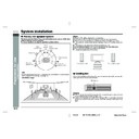
Placing the speaker system
The best surround effect will be achieved by placing each speaker at the same
distance from the listening position.
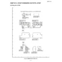
It is recommended to arrange the speakers as shown below.
distance from the listening position.
It is recommended to arrange the speakers as shown below.
Notes:
!
Place the TV halfway between the front speakers.
!
It is recommended that the centre speaker be placed near the television.
!
Place the surround speakers at a position just above the height of your ears.
!
The subwoofer vibrates whilst reproducing bass. Place it on a stable, sturdy sur-
face.
face.
!
The subwoofer reproduces bass. Place it anywhere you like.
!
Do not allow any objects to fall into or to be placed in the bass reflex ducts.
!
Front and centre speakers are magnetically shielded.
!
The speakers grilles are not removable.
"
Cooling fan
Caution:
!
The unit will get warm whilst being used. Do not touch the warm areas of the unit
for prolonged periods to avoid damage to you.
for prolonged periods to avoid damage to you.
!
A safety circuit protects the amplifier from damage. When it is activated, the sound
switch is turned off. In this case, set the unit to the stand-by mode and turn on
again.
switch is turned off. In this case, set the unit to the stand-by mode and turn on
again.
Note:
The default distance is set to 2 m. If speakers cannot be placed at equal distances,
refer to "Speaker delay setting" (see page 52).
refer to "Speaker delay setting" (see page 52).
Installation image:
Front
speaker (left)
Subwoofer
Front
speaker (right)
speaker (right)
Surround
speaker (left)
speaker (left)
Surround
speaker (right)
speaker (right)
Default setting:
2 m
2 m
Centre
speaker
This unit is fitted with a cooling fan at the rear for improved cooling. Do not cover the
opening in this section with any obstacles.
opening in this section with any obstacles.
Cooling fan
Front speaker (left)
Front speaker (right)
Centre speaker
E-12
SD-PX15H_SEEG_E.fm
04/2/9
ENGLISH
TINSZA052AWZZ
F
S
V
I
N
P
E
D
SD-PX15H
Pr
epara
tion f
o
r Us
e
- S
p
e
a
k
e
r c
onne
c
tion
-
Speaker connection
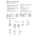
Make sure to leave the AC power lead disconnected when connecting the speakers.
Speaker terminals on the main unit and speakers, and speaker wires are distinguished by colours.
Connect the speaker and the unit by matching the colours.
(see page 13).
Connect the speaker and the unit by matching the colours.
(see page 13).
You can connect a commercially
available subwoofer with a built-
in amplifier (see page 61).
available subwoofer with a built-
in amplifier (see page 61).
Front speaker
(left)
Centre speaker
Subwoofer
Surround speaker
(left)
Surround speaker
(right)
Front speaker
(right)
Blue
Purple
White
Green
Grey
Red
(Red)
(Black)
E-13
SD-PX15H_SEEG_E.fm
04/2/9
ENGLISH
TINSZA052AWZZ
SD-PX15H
Pr
epara
tion f
o
r Us
e
- S
p
e
a
k
e
r c
onne
c
tion
-
Speaker connection (continued)
"
Connecting speaker wires
To prevent accidental short circuits between and terminals, connect the
speaker wires to the speakers first and then to the unit.
speaker wires to the speakers first and then to the unit.
!
Do not pinch the speaker wires when attaching the speaker terminal cover.
!
When the centre and surround speakers are not connected, set the speaker size
to "C-NO" and "S-NO". Otherwise, the protection circuit may be activated and the
power is turned off.
to "C-NO" and "S-NO". Otherwise, the protection circuit may be activated and the
power is turned off.
"
Speaker stand
The front speakers and surround speakers support the optional floor speaker stand
(see page 64). For installation, see the manual.
(see page 64). For installation, see the manual.
Note:
Keep the removed speaker terminal covers, speaker stands, or screw in a safe place.
Make sure to leave the AC power lead disconnected when connecting the
speakers.
speakers.
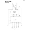
1
Remove the speaker terminal cover.
Example:
To connect the left surround speaker
To connect the left surround speaker
If screws are difficult to turn by hand, use a coin or flathead screwdriver ( ).
2
Connect the wires to the speakers.
Label (blue)
Turn it over and
route the cable
through a hole.
route the cable
through a hole.
Unscrew the
cover to remove.
cover to remove.
Red
Red
Black
Black
Speaker terminal (blue)
Tube (blue)
Tube (blue)
Connect the other end to the main unit.
Attach the speaker terminal cover.
3
4
Label (blue)
Caution:
!
The supplied speaker designed exclusively for SD-PX15H. Do not connect
speakers for SD-PX15H to other equipment. Also, do not connect other
speakers to SD-PX15H. It may cause malfunction.
speakers for SD-PX15H to other equipment. Also, do not connect other
speakers to SD-PX15H. It may cause malfunction.
!
Do not mistake the and , and right and left terminals of the speaker wires. (The
right speaker is placed on the right when you face the unit.)
right speaker is placed on the right when you face the unit.)
!
Do not let the bare speaker wires touch each other.
!
Do not stand or sit on the speakers. You may be injured.
!
Do not short-circuit the speaker wires. If the power is
turned on, malfunction may occur.
turned on, malfunction may occur.
!
When disconnecting the speaker wires, unplug the AC
power lead, and then disconnect the speaker wires from
the main unit.
power lead, and then disconnect the speaker wires from
the main unit.
E-14
SD-PX15H_SEEG_E.fm
04/2/9
ENGLISH
TINSZA052AWZZ
F
S
V
I
N
P
E
D
SD-PX15H
Pr
epara
tion f
o
r Us
e
- Ae
ri
a
l
c
o
nne
c
tion
/
TV
c
onne
c
tion
-
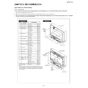
Aerial connection
Note:
Placing the aerial on the unit or near the AC power lead may cause noise pickup.
Place the aerial away from the unit for better reception.
Place the aerial away from the unit for better reception.
Installing the AM loop aerial:
External FM or AM aerial:
Use an external FM or AM aerial if you require better reception. Consult your dealer.
When using an external AM aerial, be sure to keep the wire of the AM loop aerial
connected.
When using an external AM aerial, be sure to keep the wire of the AM loop aerial
connected.
TV connection
"
Connecting to a TV with a SCART socket
Supplied FM aerial:
Connect the FM aerial wire to the FM 75 OHMS
socket and position the FM aerial wire in the di-
rection where the strongest signal can be re-
ceived.
socket and position the FM aerial wire in the di-
rection where the strongest signal can be re-
ceived.
Supplied AM loop aerial:
Connect the AM loop aerial wire to the AM and
GND terminals. Position the AM loop aerial for
optimum reception. Place the AM loop aerial on
a shelf, etc., or attach it to a stand or a wall with
screws (not supplied).
GND terminals. Position the AM loop aerial for
optimum reception. Place the AM loop aerial on
a shelf, etc., or attach it to a stand or a wall with
screws (not supplied).
< Assembling >
< Attaching to the wall >
Wall
Screws
(not
supplied)
White
Black
FM aerial
AM loop
aerial
External FM
aerial
External AM
aerial
15 m (49 feet)
7.5 m (25 feet)
AM loop
aerial
Earth wire
Earth rod
Unplug all equipment before making any connections.
Connect a TV with the supplied SCART cable.
TV
SCART cable
(supplied)
(supplied)
To SCART
input socket
input socket

