Read Sharp SD-EX100H (serv.man22) Specification online
– 3 –
SD-EX100H
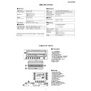
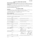
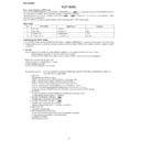
NAMES OF PARTS
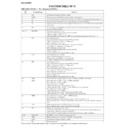
SPECIFICATIONS
Ge
■
■
neral
Amplifier
CD p
■
■
■
layer
Tuner
Speaker
Power source
AC 230 V, 50 Hz
Power consumption
Power on: 35 W
Power stand-by: 0.6 W
Dimensions
Width: 332 mm (13-1/8")
Height: 206 mm (8-1/8")
Depth: 178 mm (7")
Height: 206 mm (8-1/8")
Depth: 178 mm (7")
Weight
5.1 kg (11.2 lbs.)
Output terminals
Speakers: 4 ohms
Headphones: 16 - 50 ohms (recommended: 32 ohms)
Digital output (optical)
Input terminals
Auxiliary input: 500 mV/47 k ohms
Amplification system
64fs 1-bit switching (Remarks: fs = 44.1 kHz)
Rated output power
RMS: 50 W (25 W + 25 W) (DIN 45 324)
A/D noise shaping
7th-order
(delta - sigma) modulation
Type
1-disc slot-in type compact disc player
Signal readout
Non-contact, 3-beam semiconductor laser pickup
D/A converter
24-bit/96 k D/A converter
Frequency response
20 - 20,000 Hz
Dynamic range
90 dB (1 kHz)
Frequency range
FM: 87.5 - 108 MHz
AM: 522 - 1,620 kHz
Type
2-way type speaker system
2 cm (13/16") Tweeter
11 cm (4-3/8") Woofer
Maximum input power
50 W
Rated input power
25 W
Impedance
4 ohms
Dimensions
Width: 155 mm (6-1/8")
Height: 280 mm (11-1/16")
Depth: 210 mm (8-5/16")
Height: 280 mm (11-1/16")
Depth: 210 mm (8-5/16")
Weight
2.8 kg (6.2 lbs.)/each
Specifications for this model are subject to change without
prior notice.
prior notice.
Fr
■
■
ont panel
1. CD Compartment
2. On/Stand-by Button
3. Auxiliary Button
4. CD Play/Pause Button
5. CD Stop/Eject Button
6. CD Fast Reverse/Tuning Down Button
7. CD Fast Forward/Tuning Up Button
8. Tuner (Band) Button
9. Volume Up and Down Buttons
2. On/Stand-by Button
3. Auxiliary Button
4. CD Play/Pause Button
5. CD Stop/Eject Button
6. CD Fast Reverse/Tuning Down Button
7. CD Fast Forward/Tuning Up Button
8. Tuner (Band) Button
9. Volume Up and Down Buttons
10.Timer Set Indicator
11.Power Indicator
12.Remote Sensor
11.Power Indicator
12.Remote Sensor
Display
1. Surround Indicator
2. Random Play Indicator
3. Programme Play Indicator
4. Timer Play Indicator
5. FM Stereo Receiving Indicator
6. FM Stereo Mode Indicator
7. CD Repeat Indicator
8. Sleep Indicator
9. Function Indicators
2. Random Play Indicator
3. Programme Play Indicator
4. Timer Play Indicator
5. FM Stereo Receiving Indicator
6. FM Stereo Mode Indicator
7. CD Repeat Indicator
8. Sleep Indicator
9. Function Indicators
10.RDS Indicator
11.Radio Text Indicator
12.Traffic Programme Indicator
13.Traffic Announcement Indicator
14.Dynamic PTY Indicator
15.CD Play Indicator
11.Radio Text Indicator
12.Traffic Programme Indicator
13.Traffic Announcement Indicator
14.Dynamic PTY Indicator
15.CD Play Indicator
10
12
3
5
6
8
4
7
1
2
11
TIMER
9
2
3
4
1
5
6
6
7
8
8
9
15
10 11 12 13 14
SD-EX100H
– 4 –
R
■
■
ear panel
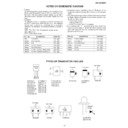
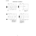
1. AC Input Socket
2. Digital Output Socket
3. Auxiliary Input Sockets
4. Speaker Terminals
5. Headphone Socket
6. FM 75 Ohms Aerial Socket
7. Aerial Earth Terminal
8. AM Aerial Terminal
2. Digital Output Socket
3. Auxiliary Input Sockets
4. Speaker Terminals
5. Headphone Socket
6. FM 75 Ohms Aerial Socket
7. Aerial Earth Terminal
8. AM Aerial Terminal
1. Speaker Grille
2. Tweeter
3. Woofer
4. Bass Reflex Duct
5. Speaker Terminals
2. Tweeter
3. Woofer
4. Bass Reflex Duct
5. Speaker Terminals
1
2
3
4
5
2
3
4
1
5
6
7
8
Speaker grilles are removable:
Make sure nothing comes into contact with
the speaker diaphragms when you remove
the speaker grilles.
the speaker diaphragms when you remove
the speaker grilles.
Speaker cushion:
Attach the cushions to the bottom of the
speakers to prevent them from sliding.
speakers to prevent them from sliding.
Rem
■
ote control
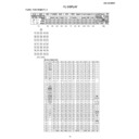
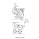
1. Remote Control Transmitter
2. On/Stand-by Button
3. CD Stop Button
4. CD Fast Reverse/Tuning Down Button
5. Auxiliary Input Button
6. Cursor/Tuner Preset Buttons
7. Volume Up and Down Buttons
8. CD Programme Button
9. Clear Button
2. On/Stand-by Button
3. CD Stop Button
4. CD Fast Reverse/Tuning Down Button
5. Auxiliary Input Button
6. Cursor/Tuner Preset Buttons
7. Volume Up and Down Buttons
8. CD Programme Button
9. Clear Button
10.Timer Button
11.Surround Button
12.CD Play Mode Select Button
13.Time Display/Dimmer Button
14.CD Play/Pause Button
15.Preset Equaliser Button
16.CD Fast Forward/Tuning Up Button
17.Tuner (Band) Button
18.Enter Button
19.Extra Bass Button
20.CD/Tuner Direct Buttons
21.CD Time Display Button
22.RDS ASPM (Auto Station Programme Memory) Button
23.RDS Programme Type/Traffic Information Search Button
24.RDS Display Button
2
3
4
5
1
6
8
9
7
10
11
13
14
15
16
17
18
19
20
21
12
22
23
24
Buttons with " " mark in the illustration can be operated on the remote control only.
Display

