Read Sharp SD-EX100H (serv.man21) Service Manual online
– 1 –
SD-EX100H
SERVICE MANUAL
SHARP CORPORATION
No. S6249SDEX100H
SD-EX100H
MODEL
1-BIT DIGITAL AUDIO SYSTEM
SD-EX100H 1-Bit Digital Audio System consisting of SD-EX100H
(main unit) and CP-EX100H (speaker system).
(main unit) and CP-EX100H (speaker system).
• In the interests of user-safety the set should be restored to its original
condition and only parts identical to those specified should be used.
CONTENTS
Page
SAFETY PRECAUTION OF CD SECTION FOR SERVICE MANUAL .............................................................................. 2
IMPORTANT SERVICE NOTES (FOR U.K. ONLY) .......................................................................................................... 2
SPECIFICATIONS ............................................................................................................................................................. 3
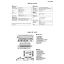
NAMES OF PARTS ........................................................................................................................................................... 3
DISASSEMBLY .................................................................................................................................................................. 5
REMOVING AND REINSTALLING THE MAIN PARTS ..................................................................................................... 8
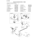
WIRING PROCESS DIAGRAM ......................................................................................................................................... 8
EXPLANATION OF CD MECHANISM ............................................................................................................................... 9
ADJUSTMENT ................................................................................................................................................................. 14
DESCRIPTION OF CIRCUIT FOR 1-BIT UNIT ............................................................................................................... 16
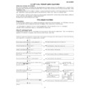
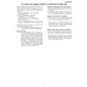
TO CHECK AND CANCEL PROTECT CIRCUIT DETECTION LINE .............................................................................. 17
TEST MODE .................................................................................................................................................................... 18
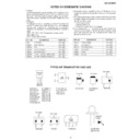
NOTES ON SCHEMATIC DIAGRAM .............................................................................................................................. 23
TYPES OF TRANSISTOR AND LED ............................................................................................................................... 23
VOLTAGE ........................................................................................................................................................................ 24
BLOCK DIAGRAM ........................................................................................................................................................... 25
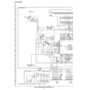
SCHEMATIC DIAGRAM .................................................................................................................................................. 30
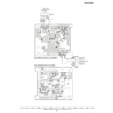
WIRING SIDE OF P.W.BOARD ....................................................................................................................................... 45
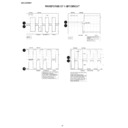
WAVEFORMS OF 1-BIT CIRCUIT .................................................................................................................................. 58
WAVEFORMS OF CD CIRCUIT ...................................................................................................................................... 59
CD OPTICAL PICKUP LENS CLEANING ........................................................................................................................ 61
TROUBLESHOOTING ..................................................................................................................................................... 61
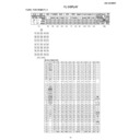
FUNCTION TABLE OF IC ................................................................................................................................................ 66
CONNECTION OF EXTENSION CABLE ........................................................................................................................ 80
FL DISPLAY ..................................................................................................................................................................... 85
PARTS GUIDE/EXPLODED VIEW
SD-EX100H
– 2 –
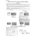
Precaution to be taken when replacing and servicing the Laser Pickup.
The AEL (Accessible Emission Level) of Laser Power Output for this model is specified to be lower than Class 1 Requirements.
However, the following precautions must be observed during servicing to protect your eyes against exposure to the Laser
beam.
(1) When the cabinet has been removed, the power is turned on without a compact disc, and the Pickup is on a position outer
than the lead-in position, the Laser will light for several seconds to detect a disc. Do not look into the Pickup Lens.
(2) The Laser Power Output of the Pickup inside the unit and replacement service parts have already been adjusted prior to
shipping.
(3) No adjustment to the Laser Power should be attempted when replacing or servicing the Pickup.
(4) Under no circumstances look directly into the Pickup Lens at any time.
(5) CAUTION - Use of controls or adjustments, or performance of procedures other than those specified herein may result in
(4) Under no circumstances look directly into the Pickup Lens at any time.
(5) CAUTION - Use of controls or adjustments, or performance of procedures other than those specified herein may result in
hazardous radiation exposure.
(Except for U.K.)
WARNINGS
SAFETY PRECAUTION OF CD SECTION FOR SERVICE MANUAL
Laser Diode Properties
Material: GaAIAs
Wavelength: 780 nm
Emission Duration: continuous
Laser Output: max. 0.6 mW
Wavelength: 780 nm
Emission Duration: continuous
Laser Output: max. 0.6 mW
ADVERSEL-SYNLIG OG USYNLIG LASERSTRÅLING VED ÅBNING. SE IKKE IND I
STRÅLEN-HELLER IKKE MED OPTISKE INSTRUMENTER.
STRÅLEN-HELLER IKKE MED OPTISKE INSTRUMENTER.
VARO! AVATTAESSA OLET ALTTIINA NÄKYVÄLLE JA NÄKYMÄTTÖMÄLLE
LASERSÄTEILYLLE ÄLÄ TUIJOTA SÄTEESEEN ÄLÄKÄ KATSO SITÄ OPTISEN
LAITTEEN LÄPI.
LASERSÄTEILYLLE ÄLÄ TUIJOTA SÄTEESEEN ÄLÄKÄ KATSO SITÄ OPTISEN
LAITTEEN LÄPI.
VARNING-SYNLIG OCH OSYNLIG LASERSTRÅLNING NÄR DENNA DEL ÄR
ÖPPNAD. STIRRA EJ IN I STRÅLEN OCH BETRAKTA EJ STRÅLEN GENOM
OPTISKT INSTRUMENT.
ÖPPNAD. STIRRA EJ IN I STRÅLEN OCH BETRAKTA EJ STRÅLEN GENOM
OPTISKT INSTRUMENT.
VAROITUS! LAITTEEN KÄYTTÄMINEN MUULLA KUIN TÄSSÄ
KÄYTTÖOHJEESSA MAINITULLA TAVALLA SAATTAA ALTISTAA
KÄYTTÄJÄN TURVALLISUUSLUOKAN 1 YLITTÄVÄLLE NÄKYMÄTTÖMÄLLE
LASERSÄTEILYLLE.
KÄYTTÖOHJEESSA MAINITULLA TAVALLA SAATTAA ALTISTAA
KÄYTTÄJÄN TURVALLISUUSLUOKAN 1 YLITTÄVÄLLE NÄKYMÄTTÖMÄLLE
LASERSÄTEILYLLE.
VARNING - OM APPARATEN ANVÄNDS PÅ ANNAT SÄTT ÄN I DENNA
BRUKSANVISNING SPECIFICERAS. KAN ANVÄNDAREN UTSÄTTAS FÖR
OSYNLIG LASERSTRÅLNING, SOM ÖVERSKRIDER GRÄNSEN FÖR
LASERKLASS 1.
BRUKSANVISNING SPECIFICERAS. KAN ANVÄNDAREN UTSÄTTAS FÖR
OSYNLIG LASERSTRÅLNING, SOM ÖVERSKRIDER GRÄNSEN FÖR
LASERKLASS 1.
Laser Diode Properties
Material: GaAIAs
Wavelength: 780 nm
Emission Duration: continuous
Laser Output: max. 0.6 mW
Wavelength: 780 nm
Emission Duration: continuous
Laser Output: max. 0.6 mW
IMPORTANT SERVICE NOTES (FOR U.K. ONLY)
Before returning the unit to the customer after completion of a
repair or adjustment it is necessary for the following withstand
voltage test to be applied to ensure the unit is safe for the
customer to use.
Setting of Withstanding Voltage Tester and set.
repair or adjustment it is necessary for the following withstand
voltage test to be applied to ensure the unit is safe for the
customer to use.
Setting of Withstanding Voltage Tester and set.
Set name
set value
Withstanding Voltage Tester
Test voltage
4,240 VPEAK
3,000 VRMS
3,000 VRMS
Set time
6 secs
Set current (Cutoff current)
4 mA
Unit
Judgment
OK: The “GOOD” lamp lights.
NG: The “NG” lamp lights and the buzzer sounds.
NG: The “NG” lamp lights and the buzzer sounds.
PROBE
AC
OUT
UNIT
SHORT-CIRCUIT
AC POWER
SUPPLY CORD
AC POWER
SUPPLY CORD
CONNECT THE PROBE
TO GND OF CHASSIS
SCREW
TO GND OF CHASSIS
SCREW
WITHSTANDING
VOLTAGE TESTER
(For U.K.)
– 3 –
SD-EX100H
NAMES OF PARTS
SPECIFICATIONS
Ge
■
■
neral
Amplifier
CD p
■
■
■
layer
Tuner
Speaker
Power source
AC 230 V, 50 Hz
Power consumption
Power on: 35 W
Power stand-by: 0.6 W
Dimensions
Width: 332 mm (13-1/8")
Height: 206 mm (8-1/8")
Depth: 178 mm (7")
Height: 206 mm (8-1/8")
Depth: 178 mm (7")
Weight
5.1 kg (11.2 lbs.)
Output terminals
Speakers: 4 ohms
Headphones: 16 - 50 ohms (recommended: 32 ohms)
Digital output (optical)
Input terminals
Auxiliary input: 500 mV/47 k ohms
Amplification system
64fs 1-bit switching (Remarks: fs = 44.1 kHz)
Rated output power
RMS: 50 W (25 W + 25 W) (DIN 45 324)
A/D noise shaping
7th-order
(delta - sigma) modulation
Type
1-disc slot-in type compact disc player
Signal readout
Non-contact, 3-beam semiconductor laser pickup
D/A converter
24-bit/96 k D/A converter
Frequency response
20 - 20,000 Hz
Dynamic range
90 dB (1 kHz)
Frequency range
FM: 87.5 - 108 MHz
AM: 522 - 1,620 kHz
Type
2-way type speaker system
2 cm (13/16") Tweeter
11 cm (4-3/8") Woofer
Maximum input power
50 W
Rated input power
25 W
Impedance
4 ohms
Dimensions
Width: 155 mm (6-1/8")
Height: 280 mm (11-1/16")
Depth: 210 mm (8-5/16")
Height: 280 mm (11-1/16")
Depth: 210 mm (8-5/16")
Weight
2.8 kg (6.2 lbs.)/each
Specifications for this model are subject to change without
prior notice.
prior notice.
Fr
■
■
ont panel
1. CD Compartment
2. On/Stand-by Button
3. Auxiliary Button
4. CD Play/Pause Button
5. CD Stop/Eject Button
6. CD Fast Reverse/Tuning Down Button
7. CD Fast Forward/Tuning Up Button
8. Tuner (Band) Button
9. Volume Up and Down Buttons
2. On/Stand-by Button
3. Auxiliary Button
4. CD Play/Pause Button
5. CD Stop/Eject Button
6. CD Fast Reverse/Tuning Down Button
7. CD Fast Forward/Tuning Up Button
8. Tuner (Band) Button
9. Volume Up and Down Buttons
10.Timer Set Indicator
11.Power Indicator
12.Remote Sensor
11.Power Indicator
12.Remote Sensor
Display
1. Surround Indicator
2. Random Play Indicator
3. Programme Play Indicator
4. Timer Play Indicator
5. FM Stereo Receiving Indicator
6. FM Stereo Mode Indicator
7. CD Repeat Indicator
8. Sleep Indicator
9. Function Indicators
2. Random Play Indicator
3. Programme Play Indicator
4. Timer Play Indicator
5. FM Stereo Receiving Indicator
6. FM Stereo Mode Indicator
7. CD Repeat Indicator
8. Sleep Indicator
9. Function Indicators
10.RDS Indicator
11.Radio Text Indicator
12.Traffic Programme Indicator
13.Traffic Announcement Indicator
14.Dynamic PTY Indicator
15.CD Play Indicator
11.Radio Text Indicator
12.Traffic Programme Indicator
13.Traffic Announcement Indicator
14.Dynamic PTY Indicator
15.CD Play Indicator
10
12
3
5
6
8
4
7
1
2
11
TIMER
9
2
3
4
1
5
6
6
7
8
8
9
15
10 11 12 13 14
SD-EX100H
– 4 –
R
■
■
ear panel
1. AC Input Socket
2. Digital Output Socket
3. Auxiliary Input Sockets
4. Speaker Terminals
5. Headphone Socket
6. FM 75 Ohms Aerial Socket
7. Aerial Earth Terminal
8. AM Aerial Terminal
2. Digital Output Socket
3. Auxiliary Input Sockets
4. Speaker Terminals
5. Headphone Socket
6. FM 75 Ohms Aerial Socket
7. Aerial Earth Terminal
8. AM Aerial Terminal
Speaker system
1. Speaker Grille
2. Tweeter
3. Woofer
4. Bass Reflex Duct
5. Speaker Terminals
2. Tweeter
3. Woofer
4. Bass Reflex Duct
5. Speaker Terminals
1
2
3
4
5
2
3
4
1
5
6
7
8
Speaker grilles are removable:
Make sure nothing comes into contact with
the speaker diaphragms when you remove
the speaker grilles.
the speaker diaphragms when you remove
the speaker grilles.
Speaker cushion:
Attach the cushions to the bottom of the
speakers to prevent them from sliding.
speakers to prevent them from sliding.
Rem
■
ote control
1. Remote Control Transmitter
2. On/Stand-by Button
3. CD Stop Button
4. CD Fast Reverse/Tuning Down Button
5. Auxiliary Input Button
6. Cursor/Tuner Preset Buttons
7. Volume Up and Down Buttons
8. CD Programme Button
9. Clear Button
2. On/Stand-by Button
3. CD Stop Button
4. CD Fast Reverse/Tuning Down Button
5. Auxiliary Input Button
6. Cursor/Tuner Preset Buttons
7. Volume Up and Down Buttons
8. CD Programme Button
9. Clear Button
10.Timer Button
11.Surround Button
12.CD Play Mode Select Button
13.Time Display/Dimmer Button
14.CD Play/Pause Button
15.Preset Equaliser Button
16.CD Fast Forward/Tuning Up Button
17.Tuner (Band) Button
18.Enter Button
19.Extra Bass Button
20.CD/Tuner Direct Buttons
21.CD Time Display Button
22.RDS ASPM (Auto Station Programme Memory) Button
23.RDS Programme Type/Traffic Information Search Button
24.RDS Display Button
2
3
4
5
1
6
8
9
7
10
11
13
14
15
16
17
18
19
20
21
12
22
23
24
Buttons with " " mark in the illustration can be operated on the remote control only.

