Read Sharp QT-CD180 (serv.man4) Service Manual online
QT-CD180H/QT-CD180W
– 18 –
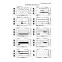
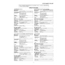
NOTES ON SCHEMATIC DIAGRAM
SW102
RECODE/PLAYBACK
REC—P.B.
SW201
FUNCTION SELECTOR
TAPE/OFF—AM/ON—
FM/ON—CD/ON
FM/ON—CD/ON
SW302
X-BASS
OFF—ON
SW303
BEAT CANCEL
A—B
(QT-CD180W ONLY)
SW601
TAPE MAIN
OFF—ON
SW651
VOLTAGE SELECTOR
AC220-240V—
(QT-CD180W ONLY)
AC110-127V
SW702
PICKUP IN
OFF—ON
SW801
PLAY/PAUSE
OFF—ON
SW802
STOP
OFF—ON
SW803
TRACK DOWN/REVIEW
OFF—ON
SW804
TRACK UP/CUE
OFF—ON
SW810
CD LID
OFF—ON
REF. NO
DESCRIPTION
POSITION
E C B
(S) (G) (D)
(1) (2) (3)
FRONT
VIEW
KRC107 M
KTA1046 Y
KTA1266 GR
KTA1273 Y
KTC3199 GR
KTA1046 Y
KTA1266 GR
KTA1273 Y
KTC3199 GR
TYPES OF TRANSISTOR
•
Resistor:
•
Capacitor:
•
Schematic diagram and Wiring Side of P.W.Board for this
• The indicated voltage in each section is the one measured by
Digital Multimeter between such a section and the chassis
with no signal given.
with no signal given.
1. Tuner
( ) : AM mode
: FM mode
: FM mode
2. CD
( ) : Stop state
: Play mode
: Play mode
3. Deck section
Stop mode
• Schematic diagram and Wiring Side of P.W.Board for this
• Parts marked with “ ” (
) are important for
maintaining the safety of the set. Be sure to replace these
parts with specified ones for maintaining the safety and
performance of the set.
parts with specified ones for maintaining the safety and
performance of the set.

