Read Sharp HT-M700H (serv.man9) Service Manual online
HT-M700H
8 – 1
HT-M700H
Service Manual
CHAPTER 8.
OTHER
[1] Function table of IC
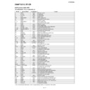
U1A VHiES6698FD-1: Decoder (ES6698FD) (1/3)
In this unit, the terminal with asterisk mark (*) is (open) terminal which is not connected to the outside.
Pin No.
Terminal Name
Input/Output
Function
1
VD33
Input
I/O power supply.
2
VID_XI
Input
Crystal input.
3
VID_XO
Output
Crystal output.
4*
CLK
Input
System clock.
5-8
DMA0-DMA3
Output
DRAM address bus.
9
VS33
–
Ground for I/O power supply.
10
VD33
Input
I/O power supply.
11-17
DMA4-DMA10
Output
DRAM address bus.
18
VS33
–
Ground for I/O power supply.
19
VD33
Input
I/O power supply.
20
DMA11
Output
DRAM address bus.
21
DCAS#
Output
DRAM column address strobe (active-low).
22, 23*
DCS0#, DCS1#
Output
DRAM chip select (active-low).
24, 25
DRAS0#, DRAS1#
Output
DRAM row address strobe (active-low).
26
VSS
–
Ground for core power supply.
27
VDD
Input
Core power supply.
28
DRAS2#
Output
DRAM row address strobe (active-low).
29
DSCK_EN
Output
DRAM clock enable output.
DOE#
Output
DRAM output enable (active-low).
30
DWE#
Output
DRAM write enable (active-low).
31-33
DB0-DB2
Input/Output
DRAM data bus.
34
VS33
–
Ground for I/O power supply.
35
VD33
Input
I/O power supply.
36-40
DB3-DB7
Input/Output
DRAM data bus.
41, 42
DB15, DB14
Input/Output
DRAM data bus.
43
VS33
–
Ground for I/O power supply.
44
VD33
Input
I/O power supply.
45-50
DB13-DB8
Input/Output
DRAM data bus.
51
DSCK
Output
Output clock to DRAM.
52
VS33
–
Ground for I/O power supply.
53
VD33
Input
I/O power supply.
54
DQM
Output
Data input/output mask.
55-60
LA21-LA16
Output
RISC port address bus.
61
VS33
–
Ground for I/O power supply.
62
VD33
Input
I/O power supply.
63-69
LA15-LA9
Output
RISC port address bus.
70
VSS
–
Ground for core power supply.
71
VDD
Input
Core power supply.
72-77
LA8-LA3
Output
RISC port address bus.
78
VS33
–
Ground for I/O power supply.
79
VD33
Input
I/O power supply.
80-82
LA2-LA0
Output
RISC port address bus.
83*-85 (84*) LCS0#-LCS2#
Output
RISC port chip select (active-low).
86
VSS
–
Ground for core power supply.
87
VDD
Input
Core power supply.
88
LCS3#
Output
RISC port chip select (active-low).
89
LWRLL#
Output
RISC port low-byte write enable (active-low).
90
LOE#
Output
RISC port output enable (active-low).
91-94
LD0-LD3
Input/Output
RISC port data bus; (5 V tolerant input).
95
VS33
–
Ground for I/O power supply.
96
VD33
Input
I/O power supply.
97-100
LD4-LD7
Input/Output
RISC port data bus; (5 V tolerant input).
101
RSD
Input
Audio receive serial data; (5 V tolerant input).
102
RBCK
Input
Audio receive bit clock; (5 V tolerant input).
103
RWS
Input
Audio receive frame sync; (5 V tolerant input).
104
VD33_PL
Input
Power for PLL blocks.
105
VS33_PL
–
Ground for PLL blocks.
HT-M700H
8 – 2
U1A VHiES6698FD-1: Decoder (ES6698FD) (2/3)
In this unit, the terminal with asterisk mark (*) is (open) terminal which is not connected to the outside.
Pin No.
Terminal Name
Input/Output
Function
106
VREF
Input
Internal voltage reference to video DAC.
YUV1
Output
YUV pixel 1 output data.
107
COMP
Input
Compensation input.
YUV3
Output
YUV pixel 3 output data.
108
REST
Input
DAC current adjustment resistor input.
YUV4
Output
YUV pixel 4 output data.
109
FDAC
Output
Video DAC output.
YUV7
Output
YUV pixel 7 output data.
110
VDAC
Output
Video DAC output.
YUV6
Output
YUV pixel 6 output data.
111
VD33_DA
Input
Power for I/O power supply for VDAC.
112
VS33_DA
–
Ground for I/O power supply for VDAC.
113
YDAC
Output
Video DAC output.
YUV5
Output
YUV pixel 5 output data.
114
CDAC
Output
Video DAC output.
YUV2
Output
YUV pixel 2 output data.
115
UDAC
Output
Video DAC output.
YUV0
Output
YUV pixel 0 output data.
116
TWS
Output
Audio transmit frame sync output.
SEL_PLL2
Input
System and DSCK output clock frequency selection is made at the rising edge of RESET#.
The matrix below lists the available clock frequencues and their respective PLL bit set-
tings.
Strapped to VCC or ground via 4.7 kohms resistor; read only during reset.
The matrix below lists the available clock frequencues and their respective PLL bit set-
tings.
Strapped to VCC or ground via 4.7 kohms resistor; read only during reset.
117
TSD0
Output
Audio transmit serial data port 0.
SEL_PLL0
Input
System and DSCK output clock frequency selection is made at the rising edge of RESET#.
The matrix below lists the available clock frequencues and their respective PLL bit set-
tings.
Strapped to VCC or ground via 4.7 kohms resistor; read only during reset.
The matrix below lists the available clock frequencues and their respective PLL bit set-
tings.
Strapped to VCC or ground via 4.7 kohms resistor; read only during reset.
118
TSD1
Output
Audio transmit serial data port 1.
SEL_PLL1
Input
System and DSCK output clock frequency selection is made at the rising edge of RESET#.
The matrix below lists the available clock frequencues and their respective PLL bit set-
tings.
Strapped to VCC or ground via 4.7 kohms resistor; read only during reset.
The matrix below lists the available clock frequencues and their respective PLL bit set-
tings.
Strapped to VCC or ground via 4.7 kohms resistor; read only during reset.
119
VS33
–
Ground for I/O power supply.
120, 121*
TSD2, TSD3
Output
Audio transmit serial data port 2 and 3.
122
MCLK
Input/Output
Audio master clock for audio DAC.
123
TBCK
Output
Audio transmit bit clock.
124
SPD_DOBM
Output
S/PDIF output.
SEL_PLL3
Input
Clock source select. Strapped to VCC or ground via 4.7 kohms resistor; read only during
reset.
reset.
125
SPDIF_IN
Input
S/PDIF input; (5 V tolerant input).
126
VD33
Input
I/O power supply.
127
VS33
–
Ground for I/O power supply.
128
WBLCLK
Output
DVD-RAM wobble detector circuit clock source to preamp.
129
WBL
Output
DVD-RAM wobble output.
130*
LG
Output
DVD-RAM land/groove flag.
131
IP2
Input
DVD-RAM header position index 2.
132
IP1
Input
DVD-RAM header position index 1.
133*-136*
FLAG0-FLAG3
Output
To minitor servo status.
137
VSS
–
Ground for core power supply.
138
VDD
Input
Core power supply.
139
TEXI
Input
High-speed tracking error input.
140
TESTAD
Input
Test AD input.
141
SBAD
Input
Sub-beam addition input signal.
142
FEI
Input
Focus input error signal.
143
AVSS_AD
–
Analog ground for ADC block.
144
CEI
Input
Center error input signal.
145
TEI
Input
Tracking error input signal.
146
RFRP
Input
RF ripple/envelope input signal.
147
AVDD3_AD
Input
Analog power supply for ADC block.
148
VREF21
Output
2.1 V reference voltage.
HT-M700H
8 – 3
U1A VHiES6698FD-1: Decoder (ES6698FD) (3/3)
In this unit, the terminal with asterisk mark (*) is (open) terminal which is not connected to the outside.
Pin No.
Terminal Name
Input/Output
Function
149
VREF09
Output
0.9 V reference voltage.
150
VREF15
Output
1.5 V reference voltage.
151
IREF
Input
Servo data PLL interface reference current generator. Connect a resistor between this pin
and ground to set reference current.
and ground to set reference current.
152
AVDD3_DS
Input
Analog power supply for data slicer block.
153
IPIN
Input
Inverting input of data slicer.
154
RFIN
Input
Analog RF signal input after passing through equalizer (minus).
155
RFIP
Input
Analog RF signal input after passing through equalizer (plus).
156
DSSLV
Output
Data slicer level output.
157
AVSS_DS
–
Analog ground for data slicer block.
158
AVSS_PL
–
Analog ground for data PLL block.
159
PDOFTR1
Output
Servo data PLL phase detector filter pin number 1.
160
FDO
Output
Servo data PLL output node of frequency detector charge pump.
161
FTROPI
Input
Aervo data PLL input node of loop filter OP circuit.
162
AVDD3_PL
Input
Analog power supply for data PLL block.
163
PLLFTR1
Input
Servo data PLL loop filter pin number 1.
164
PLLFTR2
Input
Servo data PLL loop filter pin number 2.
165
VREF0
Output
Servo data PLL reference voltage output.
166
AWRC
Input/Output
Auto wide range control VCO signal from/to AWRC DAC.
167
AVSS_DA
–
Analog ground for DAC part.
168
RFRPCTR
Input/Output
Central level of RFRP.
169
TRAY
Output
Output voltage level for tray buffer IC.
170
AVDD3_DA
Input
Analog power supply for DAC part.
171
SPINDLE
Output
Outpur voltage level for spindle buffer IC.
172
FOCUS
Output
Outpur voltage level for focus buffer IC.
173*
SLEGP
Output
Outpur voltage level for Sledge buffer IC (plus).
174
SLEGN
Output
Outpur voltage level for Sledge buffer IC (minus).
175
TRACK
Output
Outpur voltage level for tracking buffer IC.
176
TESTDA
Output
Test DA output.
177*
FGIN
Input
Spindle hall sensor input.
178*
PHOI
Input
Sledge photo interrupt signal input.
179
SCSJ
Output
Chip selection signal to RF chip (serial data enable).
180
SDATA
Input/Output
Data signal from/to RF chip.
181
SCLK
Output
Serial clock source to RF chip.
182
DFCT
Input
Defect flaginput signal.
183
LDC
Output
Laser diode on/off control output.
184
SPDON
Output
Spindle power driver on/off control output.
185
VD33
Input
I/O power supply.
186
VS33
–
Ground for I/O power supply.
187-192
GPIO9-GPIO4
Input/Output
General-purpose input/output used for servo control; (5 V tolarant input).
193-196
EAUX3-EAUX0
Input/Output
Extended auxiliary ports; (5 V tolarant input).
197
VSS
–
Ground for core power supply.
198
VDD
Input
Core power supply.
199
I
2
CDATA
Input/Output
I
2
C data I/O; (5 V tolarant input).
AUX0
Input/Output
Auxiliary port (open collector); (5 V tolarant input).
200
I
2
C_CLK
Input/Output
I
2
C clock I/O; (5 V tolarant input).
AUX1
Input/Output
Auxiliary port (open collector); (5 V tolarant input).
201
IOW#
Output
I/O Write strobe (LCS1) (active-low).
HSYNC#
Input/Output
Horizontal sync (active-low); (5 V tolarant input).
AUX2
Input/Output
Auxiliary port (open collector); (5 V tolarant input).
202
IOR#
Output
I/O Read strobe (LCS1) (active-low).
VSYNC#
Input/Output
Vertical sync (active-low); (5 V tolarant input).
AUX3
Input/Output
Auxiliary port (open collector); (5 V tolarant input).
203
C2PO
Input
Error correction flag from CD; (5 V tolarant input).
AUX4
Input/Output
Auxiliary port (open collector); (5 V tolarant input).
204, 205
AUX5, AUX6
Input/Output
Auxiliary ports (open collector); (5 V tolarant input).
206
IR
Input
Infrared remote control input; (5 V tolarant input).
AUX7
Input/Output
Auxiliary port (open collector); (5 V tolarant input).
207
RESET#
Input
Reset input (active-low); (5 V tolarant input).
208
VS33
–
Ground for I/O power supply.
HT-M700H
8 – 4
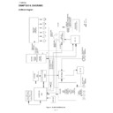
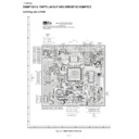
U1A VHiES6698FD-1: Decoder (ES6698FD)
Figure 8-4 BLOCK DIAGRAM OF IC
VS33
208
VD33
1
VID_XI
2
VID_XO
3
CLK
4
DMA0
5
DMA1
6
DMA2
7
DMA3
8
VS33
9
VD33
10
DMA4
11
DMA5
12
DMA6
13
DMA7
14
DMA8
15
DMA9
16
DMA10
17
VS33
18
VD33
19
DMA1
1
20
DCAS#
21
DCS0#
22
DCS1#
23
DRAS0#
24
DRAS1#
25
VSS
26
VDD
27
DRAS2#
28
DSCK_EN/DOE#
29
DWE#
30
DB0
31
DB1
32
DB2
33
VS33
34
VD33
35
DB3
36
DB4
37
DB5
38
DB6
39
DB7
40
DB15
41
DB14
42
VS33
43
VD33
44
DB13
45
DB12
46
DB1
1
47
DB10
48
DB9
49
DB8
50
DSCK
51
VS33
52
DSSL
V
156
RFIP
155
RFIN
154
IPIN
153
AV
DD3_DS
152
IREF
151
VREF15
150
VREF09
149
VREF21
148
AV
DD3_AD
147
RFRP
146
TEI
145
CEI
144
AV
SS_AD
143
FEI
142
SBAD
141
TEST
AD
140
TEXI
139
VDD
138
VSS
137
FLAG3
136
FLAG2
135
FLAG1
134
FLAG0
133
IP1
132
IP2
131
LG
130
WBL
129
WBLCLK
128
VS33
127
VD33
126
SPDIF_IN
125
SPD_DOBM/SEL_PLL3
124
TBCK
123
MCLK
122
TSD3
121
TSD2
120
VS33
11
9
TSD1/SEL_PLL1
11
8
TSD0/SEL_PLL0
11
7
TWS/SEL_PLL2
11
6
UDAC/YUV0
11
5
CDAC/YUV2
11
4
YDAC/YUV5
11
3
VS33_DA
11
2
VS33_DA
111
VDAC/YUV6
11
0
FDAC/YUV7
109
RSET/YUV4
108
COMP/YUV3
107
VREF/YUV1
106
VS33_PL
105
RESET#
207
IR/AUX7
206
AUX6
205
AUX5
204
C2PO/AUX4
203
IOR#/VSYNC#/AUX3
202
IOW#/HSYNC#/AUX2
201
I
2
C_CLK/AUX1
200
I
2
CDATA/AUX0
199
VDD
198
VSS
197
EAUX0
196
EAUX1
195
EAUX2
194
EAUX3
193
GPIO4
192
GPIO5
191
GPIO6
190
GPIO7
189
GPIO8
188
GPIO9
187
VS33
186
VD33
185
SPDON
184
LDC
183
DFCT
182
SCLK
181
SDATA
180
SCSJ
179
ES6698
PHOI
178
FGIN
177
TESTDA
176
TRACK
175
SLEGN
174
SLEGP
173
FOCUS
172
SPINDLE
171
AVDD3_DA
170
TRAY
169
RFRPCTR
168
AVSS_DA
167
AWRC
166
VREF0
165
PLLFTR2
164
PLLFTR1
163
AVDD3_PL
162
FTROPI
161
FDO
160
PDOFTR1
159
AVSS_PL
158
AVSS_DS
157
VD33
53
DQM
54
LA21
55
LA20
56
LA19
57
LA18
58
LA17
59
LA16
60
VS33
61
VD33
62
LA15
63
LA14
64
LA13
65
LA12
66
LA11
67
LA10
68
LA9
69
VSS
70
VDD
71
LA8
72
LA7
73
LA6
74
LA5
75
LA4
76
LA3
77
VS33
78
VD33
79
LA2
80
LA1
81
LA0
82
LCS0#
83
LCS1#
84
LCS2#
85
VSS
86
VDD
87
LCS3#
88
LWRLL#
89
LOE#
90
LD0
91
LD1
92
LD2
93
LD3
94
VS33
95
VD33
96
LD4
97
LD5
98
LD6
99
LD7
100
RSD
101
RBCK
102
RWS
103
VD33_PL
104

