Read Sharp CD-RW5000 (serv.man25) Service Manual online
– 27 –
CD-RW5000H/CD-RW5000W
MECHANISM SECTION
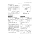
• Driving Force Check
Torque Meter
Specified Value
Play: TW-2412
Over 80 g
• Torque Check
Torque Meter
Play: TW-2111
30 to 60 g.cm
Fast forward: TW-2231
60 to 120 g.cm
Rewind: TW-2231
60 to 120 g.cm
Specified
Value
Adjusting
Point
Instrument
Connection
Test Tape
ADJUSTMENT
Specified Value
• Tape Speed
MTT-111
Variable
3,000
±
90 Hz
Speaker
resistor in
Terminal
motor.
TUNER SECTION
Adjusting
Parts
Display
Frequency
• FM Mute Level (FM ST MODE)
Signal generator: 1 kHz, 40 kHz dev., FM modulated
Signal generator: 1 kHz, 40 kHz dev., FM modulated
*1. Adjust so that an output signal appears.
98.00 MHz
98.00 MHz
VR351 *1
Input: CNP303
(26 dB
µ
V)
Output: Speaker
Terminal
Instrument
Connection
*1. Input: Antenna
Output: Speaker Terminal
*2. Input: Antenna
Output: TP301
Test Stage
Frequency
Display
Setting/
Adjusting
Parts
Instrument
Connection
AM IF
450 kHz
1,620 kHz
T351
*1
AM Band
—
522 kHz
(fL): T306
*2
Coverage
1.1
±
0.1 V
AM
990 kHz
990 kHz
T302
*1
Tracking
fL: Low-range frequency
fH: High-range frequency
fH: High-range frequency
Signal generator: 400 Hz, 30%, AM modulated
• AM IF/RF
• FM RF
Signal generator: 1 kHz, 75 kHz dev., FM modulated
Signal generator: 1 kHz, 75 kHz dev., FM modulated
FM Band
—
87.50 MHz
(fL): T311
*1
Coverage
1.3
±
50 mV
FM RF
98.00 MHz
98.0 MHz
L312
*2
(10~30 dB)
Test Stage
Frequency Frequency
Display
Setting/
Adjusting
Parts
Instrument
Connection
*1. Input: Antenna
Output: TP301
*2. Input: Antenna
Output: Speaker Terminal
CD-RW5000H
*1. Input: Antenna
Output: Speaker Terminal
*2. Input: Antenna
Output: TP301
Test Stage
Frequency
Display
Setting/
Adjusting
Parts
Instrument
Connection
AM IF
450 kHz
1,602 kHz
T351
*1
AM Band
—
522 kHz
(fL): T306
*2
Coverage
1.1
±
0.1 V
AM
990 kHz
990 kHz
T302
*1
Tracking
Signal generator: 400 Hz, 30%, AM modulated
• AM IF/RF
CD-RW5000W
• FM
Notes:
1: Description of the "FM IF Adjustment" is not carried on this
Notes:
1: Description of the "FM IF Adjustment" is not carried on this
Manual. It is because the IF coil in the FM front end section
has been best adjusted in the factory so that its further
adjustment is not needed at the field. When replacing the
FM front end assembly, no adjustment is needed either.
has been best adjusted in the factory so that its further
adjustment is not needed at the field. When replacing the
FM front end assembly, no adjustment is needed either.
2: The parts in the FM front end section are prepared in a
complete unit, so you can't obtain each part individually.
Adjusting
Parts
Display
Frequency
• FM Mute Level (FM ST MODE)
Signal generator: 1 kHz, 40 kHz dev., FM modulated
Signal generator: 1 kHz, 40 kHz dev., FM modulated
*1. Adjust so that an output signal appears.
98.00 MHz
98.00 MHz
VR351 *1
Input: CNP303
(26 dB
µ
V)
Output: Speaker
Terminal
Instrument
Connection
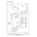
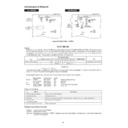
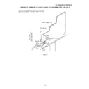
Figure 27 ADJUSTMENT POINT
TAPE MECHANISM
Variable
Resistor
in motor
Resistor
in motor
Tape motor
CD-RW5000H/CD-RW5000W
– 28 –
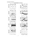
Figure 28 ADJUSTMENT POINTS
CD-RW5000H
CD-RW5000W
IC301
1
9
T306
T302
T311
L312
BF301
MAIN PWB
FM MUTE
LEVEL
LEVEL
AM IF
TP301
TP301
AM
TRACKING
TRACKING
AM BAND
COVERAGE fL
COVERAGE fL
FM BAND
COVERAGE fL
COVERAGE fL
FM RF
FM IF
VR351
T351
T312
R345
T306
T302
MAIN PWB
AM IF
CNP301
AM LOOP
ANTENNA
SO301
FM ANTENNA
TERMINAL
SO301
AM/FM
ANTENNA
TERMINAL
VR351
T351
R345
FE301
1
FM MUTE
LEVEL
LEVEL
AM
TRACKING
TRACKING
AM BAND
COVERAGE fL
COVERAGE fL
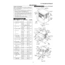
Outline
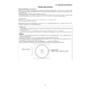
While the unit is turned off, press the POWER key while holding down the VOLUME-DOWN and PANEL OP/CL keys to enter
the test mode selection mode. Then, the unit is started, the panel is opened, and the microcomputer's version/destination/span
is displayed. If the following data is entered from the keyboard while in the test mode selection mode, the unit directly enters
the specified test mode. This operation is applied to the main unit's keys only.
In the destination display, a destination code (H/W/U/J) is displayed. For the span display, "9" means 9 kHz/50 kHz, and "10"
means 10/100 kHz. All pictures will disappear except the characters.
means 10/100 kHz. All pictures will disappear except the characters.
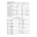
By pressing the specific key, you can enter the test mode whose functions are as follows:
Menu display
Shortcut Key
Model
System
INITIAL
CD1 PLAY
ALL
Shipping status setting
SOFT_RESET
CD2 PLAY
ALL
Soft rest
CD
CD_TEST
CD1 EJECT
ALL
CD test
Tuner
TUN_PRESET
CD4 EJECT
ALL
Tuner test frequency preset
TUNER_TEST
CD5 EJECT
ALL
Tuner test
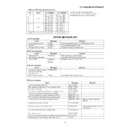
Outline of Test Mode
Shipping status setting test mode
Purpose: To set up the unit for shipping.
Function: Initialize all functions.
Operation: All settings are initialized, "FINISH" is displayed as in the sample display, and data entry is prohibited including data
Function: Initialize all functions.
Operation: All settings are initialized, "FINISH" is displayed as in the sample display, and data entry is prohibited including data
to turn on or off the unit.
TEST MODE
Version • Destination
V
*
•
*
Left adjust in the first line
Character display
Example: V1. 1_W:_9
Destination
Number
Span
Item
Type Auxiliary display
1
2
3
4
5
6
7
8
9 10
Auxiliary display
Note
1
Shipping status setting
Sets up the unit for shipping.
2
Soft set setting
Initializes the unit.
3
CD test
Performs tests such as the CD mechanism test, hardware test, and constant setting test.
4
Tuner test
Presets the test frequency.
frequency preset
5
Tuner preset clear setting
Clears all presets.
Name
Description
11 12
Display

