Read Sharp CD-RW5000 (serv.man13) Service Manual online
CD-RW5000H/CD-RW5000W
– 18 –
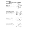
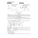
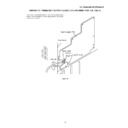
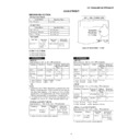
Figure 18-1
Figure 18-2
Figure 18-3
Figure 18-4
REMOVING AND REINSTALLING THE MAIN PARTS
TAPE MECHANISM SECTION
Perform steps 1 to 4 and 9 of the disassembly method to
remove the tape mechanism.
remove the tape mechanism.
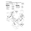
How to remove the record/playback and erase
heads (See Fig. 18-1)
heads (See Fig. 18-1)
1. When you remove the screws (A1) x 2 pcs., the recording/
playback head and three-dimensional head of the erasing
head can be removesd.
head can be removesd.
How to remove the pinch roller (See Fig. 18-2)
1. Carefully bend the pinch roller pawl in the direction of the
arrow <A>, and remove the pinch roller (B1) x1 pc., in the
direction of the arrow <B>.
direction of the arrow <B>.
Note:
When installing the pinch roller, pay attention to the spring
mounting position.
When installing the pinch roller, pay attention to the spring
mounting position.
How to remove the belt (See Fig. 18-3)
1. Remove the motor.
2. Remove the main belt (C1) x 1 pc., from the motor side.
3. Remove the FF/REW belt (C2) x 1 pc.
2. Remove the main belt (C1) x 1 pc., from the motor side.
3. Remove the FF/REW belt (C2) x 1 pc.
Main Belt
(C1)x1
(C1)x1
FF/REW Belt
(C2)x1
(C2)x1
Motor
How to remove the motor (See Fig. 18-4)
1. Remove the belt.
2. Remove the screws (D1) x 2 pcs., to remove the motor.
2. Remove the screws (D1) x 2 pcs., to remove the motor.
Pinch
Roller
(B1)x1
Roller
(B1)x1
<A>
Pinch
Roller
Pawl
Roller
Pawl
Pull
<B>
Pull
(Left)
<A>
Pinch
Roller
Pawl
Roller
Pawl
Pull
<B>
Pull
(Right)
(A1)x2
Ø2 x 6mm
Ø2 x 6mm
Record/
Playback
Head
Playback
Head
Erase
Head
Head
(D1)x2
Ø 2.6 x 5mm
Ø 2.6 x 5mm
Motor
– 19 –
CD-RW5000H/CD-RW5000W
CD MECHANISM SECTION
Perform steps 1 to 7 of the disassembly method to remove the
CD mechanism. (See page 17.)
CD mechanism. (See page 17.)
Note:
After removing the connector for the optical pickup from the
connector, wrap the conductive aluminium foil around the
front end of connector remove to protect the optical pickup
from electrostatic damage.
After removing the connector for the optical pickup from the
connector, wrap the conductive aluminium foil around the
front end of connector remove to protect the optical pickup
from electrostatic damage.
How to remove the control panel motor
(See Fig. 19-1)
(See Fig. 19-1)
1. Remove the control panel.
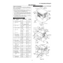
2. Remove the screws (E1) x 6 pcs., to remove the CD changer
2. Remove the screws (E1) x 6 pcs., to remove the CD changer
door panel.
3. Remove the screws (F1) x 2 pcs., to remove the control
panel motor.
How to Remove the pickup (See Fig. 19-2.)
1. Remove the screws (A1)x 2 pcs., to remove shaft (A2)x 1
pc.
2. Remove stop washer (A3)x 1 pc., to remove gear (A4)x 1 pc.
3. Remove the pickup.
3. Remove the pickup.
(A1) x1
ø2.6 x6mm
ø2.6 x6mm
CD
Mechanism
Mechanism
Stop Washer
(A3) x1
(A3) x1
Gear
(A4) x1
(A4) x1
Shaft
(A2) x1
(A2) x1
Pickup
(A1) x1
ø2.6 x6mm
ø2.6 x6mm
Figure 19-2
Figure 19-3
How to Remove the tray motor/main cam motor
(See Fig. 19-3.)
(See Fig. 19-3.)
1. Remove the screws (B1)x 4 pcs., to remove the CD PWB.
2. Remove the (1) front top plate, (2) changer box, left/right
2. Remove the (1) front top plate, (2) changer box, left/right
and (3) disc trays 1~6. After that, disassemble as shown in
the figure.
the figure.
3. Remove the screws (B2)x 4 pcs.
4. Remove the tray motor and main cam motor.
4. Remove the tray motor and main cam motor.
CD CHANGER MECHANISM SECTION
Perform steps 1 to 5 of the disassembly method to remove the
CD changer mechanism. (See page 17.)
CD changer mechanism. (See page 17.)
FRONT PANEL SECTION
Perform steps 1 to 4 of the disassembly method to remove the
front panel.
front panel.
Main Cam Motor
Tray Motor
CD PWB
(1) Front Top Plate
(2) Changer Box,
Left
Left
(2)Changer Box,
Right
Right
(3) Disc Tray,1~6
CD Changer Mechanism
(B1)x4
ø3x10mm
(B2)x4
ø2.6x4mm
Note:
The parts of (1), (2) and (3) correspond to the drawing Nos.
117, 102, 103 and 108 to 113 of the CD change mechanism
disassembly drawing.
Remove the screws of 117, 102 and 103, and the parts of (1),
(2) and (3) will be ready for removal and the screws of the tray
motor and main cam motor will be visible.
CD Changer
Door Panel
Door Panel
CD Changer
Door Panel
Door Panel
Control
Panel
Motor
Panel
Motor
Gear Box A
(E1)x1
ø2.6x10mm
ø2.6x10mm
(E1)x3
ø2.6x10mm
ø2.6x10mm
(E1)x2
ø2.6x10mm
ø2.6x10mm
(F1)x2
ø2x5mm
ø2x5mm
Motor PWB
Gear Box B
Control Panel
Figure 19-1
Display

