Read Sharp CD-CH1000 (serv.man8) Service Manual online
– 25 –
CD-CH1000H/CD-CH1000W
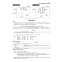
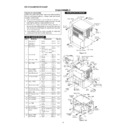
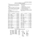
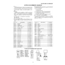
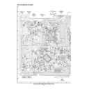
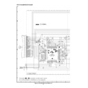
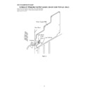
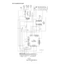
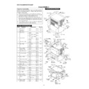
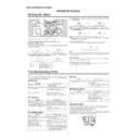
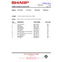
Figure 25 ADJUSTMENT POINTS
IC301
1
9
T306
T302
T311
L312
BF301
MAIN PWB
FM MUTE
LEVEL
LEVEL
AM IF
TP301
TP301
CNP303
FM/AM LOOP
ANTENNA
AM
TRACKING
TRACKING
AM BAND
COVERAGE fL
COVERAGE fL
FM BAND
COVERAGE fL
COVERAGE fL
FM RF
FM IF
VR351
T351
T312
R345
T306
T302
MAIN PWB
AM IF
CNP301
AM LOOP
ANTENNA
SO301
FM ANTENNA
TERMINAL
VR351
T351
R345
FE301
1
FM MUTE
LEVEL
LEVEL
AM
TRACKING
TRACKING
AM BAND
COVERAGE fL
COVERAGE fL
For CD-CH1000H
For CD-CH1000W
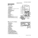
Outline
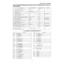
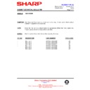
While the unit is turned off, press the POWER key while holding down the VOLUME-DOWN and PANEL OP/CL keys to enter
the test mode selection mode. Then, the unit is started, the panel is opened, and the microcomputer's version/destination/span
is displayed. If the following data is entered from the keyboard while in the test mode selection mode, the unit directly enters
the specified test mode. This operation is applied to the main unit's keys only.
In the destination display, a destination code (H/W/U/J) is displayed. For the span display, "9" means 9 kHz/50 kHz, and "10"
means 10/100 kHz. All pictures will disappear except the characters.
means 10/100 kHz. All pictures will disappear except the characters.
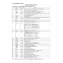
By pressing the specific key, you can enter the test mode whose functions are as follows:
Menu display
Shortcut Key
Model
System
INITIAL
CD1 PLAY
ALL
Shipping status setting
SOFT_RESET
CD2 PLAY
ALL
Soft rest
CD
CD_TEST
CD1 EJECT
ALL
CD test
Tuner
TUN_PRESET
CD4 EJECT
ALL
Tuner test frequency preset
TUNER_TEST
CD5 EJECT
ALL
Tuner test
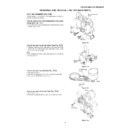
Outline of Test Mode
Shipping status setting test mode
Purpose: To set up the unit for shipping.
Function: To check the unit for a CD disc, and initialize all functions.
Operation: While checking for a CD disc, the test name (INITIAL) is displayed.
Function: To check the unit for a CD disc, and initialize all functions.
Operation: While checking for a CD disc, the test name (INITIAL) is displayed.
The initial operation for a CD disc is performed. In this operation, the unit is checked for a CD disc.
If a CD disc is found in the unit during the initial operation, "CD* OPEN" is displayed, the tray is opened (only for the
disc found first), and the unit is turned on via the CD function normally.
If no CD disc is found, the CD mechanism is placed in the chucking status.
If a CD disc is found in the unit during the initial operation, "CD* OPEN" is displayed, the tray is opened (only for the
disc found first), and the unit is turned on via the CD function normally.
If no CD disc is found, the CD mechanism is placed in the chucking status.
After the unit is checked for discs, all settings are initialized, "FINISH" is displayed as in the sample display, and data entry is
prohibited including data to turn on or off the unit.
prohibited including data to turn on or off the unit.
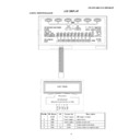
TEST MODE
Version • Destination
V
*
•
*
Left adjust in the first line
Character display
Example: V1. 1_W:_9
Destination
Number
Span
Item
Type Auxiliary display
1
2
3
4
5
6
7
8
:
9 10 Auxiliary display
Note
1
Shipping status setting
Sets up the unit for shipping.
2
Soft set setting
Initializes the unit.
3
CD test
Performs tests such as the CD mechanism test, hardware test, and constant setting test.
4
Tuner test
Presets the test frequency.
frequency preset
5
Tuner preset clear setting
Clears all presets.
Name
Description
CD-CH1000H/CD-CH1000W
– 26 –
To exit the test mode
The unit returns to the normal operation through reset entry.
Table Character display for test mode 1
In the destination display, a destination code is displayed. For the span display, "9" means 9 kHz/50 kHz, and "10" means 10/
100 kHz.
100 kHz.
2. Soft reset
Purpose: To initialize the unit.
Function: To initialize all functions.
Operation: "ALL CLEAR" is displayed, all functions are initialized, and the unit is turned on.
Function: To initialize all functions.
Operation: "ALL CLEAR" is displayed, all functions are initialized, and the unit is turned on.
To exit the test mode
When the initialization through soft reset is complete, the unit is turned on.
Table Character display for test mode 2
3. CD test mode (If this test mode is not activated, refer to CD troubleshooting on page 61.)
In the CD test mode, each step can be performed even if the LID-SW is off. However, if you cannot obtain a focus in step
3 or if other kind of error handling starts, you cannot proceed to the following steps. In error handling, press the POWER key
to exit the test mode, or press the STOP key to prohibit operations other than returning to step 1.
3 or if other kind of error handling starts, you cannot proceed to the following steps. In error handling, press the POWER key
to exit the test mode, or press the STOP key to prohibit operations other than returning to step 1.
(1) Step 1 mode
In the CD test mode, the following display appears, CD initialization is performed, and you are prompted for data.
Reset operation display / Operation
"CD_TEST"
After lighting up for one second
In the CD test mode, the following display appears, CD initialization is performed, and you are prompted for data.
Reset operation display / Operation
"CD_TEST"
After lighting up for one second
"T1___________0:00"
The keys you can press here and the resulting operations are as follows:
"POWER" ........... The test mode is turned off, the power is turned off, and the unit is placed in the normal stand-by mode.
"FWD" ................ While holding down this key, the pickup moves outward after returning to the innermost track.
"REV" ................. While holding down this key, the pickup moves inward after returning to the innermost track.
"PLAY" ............... Jumps to step 2.
"STOP" ............... Cancelled.
"TAPE REC" ...... Jumps to step 5.
* While the pickup is moving to the innermost track in the initialization, none of the keys except POWER is accepted. When PU-
IN SW ON cannot be detected in ten seconds, the unit stops the slide motor and shows the following error code. Then, you
can press the POWER key to exit the test mode, or the STOP key to return to step 1. You cannot perform other operations.
can press the POWER key to exit the test mode, or the STOP key to return to step 1. You cannot perform other operations.
"E--CD01"
(2) Step 2 mode
When the "PLAY" key is pressed in the above mode, the laser is turned on. At this time, another operation must not be
When the "PLAY" key is pressed in the above mode, the laser is turned on. At this time, another operation must not be
performed.
Display "T2___________0:00"
The keys you can press here and the resulting operations are as follows:
"POWER" ........... The test mode is turned off, the power is turned off, and the unit is placed in the normal standby mode.
"FWD" ................. While holding down this key, the pickup is moved outward.
"REV" .................. While holding down this key, the pickup is moved inward.
"PLAY" ................ Jumps to step 2.
"STOP" ............... Returns to step 1.
"TAPE REC" ....... Jumps to step 5.
Reset operation
Operation
A
L
L
C
L
E
A
R
display
Character display
Item
Type
Auxiliary display
1
2
3
4
5
6
7
8
:
9 10 Auxiliary display
Note
Test mode name
I
N
I
T
I
A
L
CD disc inserted
Operation
C
D
*
O
P E
N
Set-Up Complete
Function
F
I
N
I
S
H
Character display
Item
Type
Auxiliary display
1
2
3
4
5
6
7
8
:
9 10 Auxiliary display
Note
– 27 –
CD-CH1000H/CD-CH1000W
(3) Step 3 mode
Performs focus search and turns on the focus servo.
Focus search is repeated until it is brought into focus.
Performs focus search and turns on the focus servo.
Focus search is repeated until it is brought into focus.
Display "T3___________0:00"
The keys you can press here and the resulting operations are as follows:
"POWER" ........... The test mode is turned off, the power is turned off, and the unit is placed in the normal standby mode.
"FF/FWD" ........... While holding down this key, the pickup is moved outward.
"REW/REV" ........ While holding down this key, the pickup is moved inward.
"PLAY" ................ Jumping to step 4 when a focus is obtained. Otherwise, data entry is prohibited.
"STOP" ............... Returns to step 1.
"TAPE REC" ....... Jumps to step 5.
* You should return to step 1 if it is out of focus after bringing it into focus.
(4) Step 4 mode
Rotate a disc.
Rotate a disc.
Displayed string: "T4___________0:00"
The clock display should always be "0:00".
The keys you can press here and the resulting operations are as follows:
"POWER" ........... The test mode is turned off, the power is turned off, and the unit is placed in the normal standby mode.
"FF/FWD" ........... While holding down this key, the pickup is moved outward.
"REW/REV" ........ While holding down this key, the pickup is moved inward.
"PLAY" ................ Jumps to step 5.
"STOP" ............... Returns to step 1.
"TAPE REC" ....... Jumps to step 5.
* You should return to step 1 if it is out of focus.
(5) Step 5 mode
Start playback. When the pickup reaches the outermost track, it does not stop. The LCD screen shows the replay time elapsed
as in the normal CD playback.
as in the normal CD playback.
Display "T5___________0:00"
The keys you can press here and the resulting operations are as follows:
"POWER" ........... The test mode is turned off, the power is turned off, and the unit is placed in the normal standby mode.
"FWD" ................. While holding down this key, the pickup is moved outward.
"REV" .................. While holding down this key, the pickup is moved inward.
"PLAY" ................ Canceled.
"STOP" ............... Returns to step 1.
* You should return to step 1 if it is out of focus.
Notes:
• In the test mode, TOC IL is not performed.
• Only the keys for adjusting the volume are accepted except the keys described.
• In the test mode, TOC IL is not performed.
• Only the keys for adjusting the volume are accepted except the keys described.
4. Tuner test frequency preset
Purpose:
To preset a test frequency for an in-factory test.
Function:
To preset each preset number to the band and frequency shown in Table 24 based on the initial setting for the
destination.
destination.
Operation:
To preset the band and frequency shown in the table below and turn the unit on with the following setting.
Function
Tuner
Band
FM monaural
Tuning mode
Preset call selection
Call preset number
Preset number 1 frequency
Band's last preset channel
See Table 24
X-BASS
Off
Preset equalizer
FLAT
For other functions, the value which was set when the unit was turned off last time is valid (last state).
To exit the test mode
After the frequency is preset and the set-up is done, the unit is turned on and normal operations start.
After the frequency is preset and the set-up is done, the unit is turned on and normal operations start.
CD-CH1000H/CD-CH1000W
– 28 –
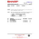
1 %
FM 87.5 MHz
FM 87.5 MHz
2
FM 108.0 MHz
FM 108.0 MHz
3
FM
FM 90.0 MHz
FM 90.0 MHz
4
FM 106.0 MHz
FM 106.0 MHz
5
FM 98.0 MHz
FM 98.0 MHz
6 %
AM 522 kHz
AM 531 kHz
7
AM 1620 kHz
AM 1602 kHz
8
AM
AM 603 kHz
AM 603 kHz
9
AM 1404 kHz
AM 1404 kHz
10
AM 990 kHz
AM 990 kHz
11-40
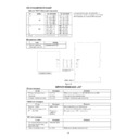
Table 24. TEST-TuSet preset frequencies
Unused channels are indicated with "—".
"%" indicates the last channel for each band.
All FM bands are preset to FM monaural.
"%" indicates the last channel for each band.
All FM bands are preset to FM monaural.
BAND
CD-CH1000H
CH
Pickup mechanism error
E-CD01
Slide motor operation error (PU-IN SW detection NG)
Tray error
E-CD20
Tray open/close operation error
Changer mechanism error
E-CD10
Changer mechanism operation error
CD error messages
Errors
Messages
Remarks
Relation to RDS
WEAK SIG
When switching to an EON station,
EON reception impossible
it cannot be received due to weak signal
.
PLL UN LOCK
Frequency
Reception error or PLL control error
indicator
flashing
flashing
TUNER error messages
Errors
Messages
Remarks
You tried to record on a tape
'PROTECTED'
TAPE mechanism error
E-TA01
Mechanism initialize abnormal end
TAPE error messages
Errors
Messages
Remarks
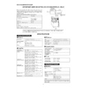
ERROR MESSAGE LIST
Type
1.
33 Pin extension
QCNWN6931AFZZ
flat cable, 500 mm
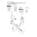
Part No.
Extension cable
CNP1
CD SERVO PWB-C
33
33
1
1
33
1
CNP901
33
1
33 pin extension flat cable
QCNWN6931AFZZ
QCNWN6931AFZZ
MAIN PWB-A
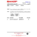
Figure 28
CD-CH1000W

