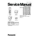
Read Panasonic KX-TG8151RUB / KX-TG8151UAB / KX-TG8151CAB / KX-TG8161RUB / KX-TG8161UAB / KX-TG8161CAB / KX-TGA815RUB Service Manual online
ORDER NO. KM41203557CE
Telephone Equipment
Model No.
KX-TG8151RUB
KX-TG8151UAB
KX-TG8151CAB
KX-TG8161RUB
KX-TG8161UAB
KX-TG8161CAB
KX-TGA815RUB
KX-TG8151UAB
KX-TG8151CAB
KX-TG8161RUB
KX-TG8161UAB
KX-TG8161CAB
KX-TGA815RUB
Digital Cordless Phone
Digital Cordless Answering System
Digital Cordless Answering System
B: Black Version
(for CIS)
(for CIS)
KX-TGA815
(Handset)
KX-TG8151
(Base Unit)
KX-TG8161
(Base Unit)
(Charger Unit)
Model No
Base Unit
Handset Charger Unit Expandable
KX-TG8151 1 (TG8151) 1 (TGA815)
Up to 6
KX-TG8161 1 (TG8161) 1 (TGA815)
Up to 6
KX-TGA815*
1 (TGA815)
1
Configuration for each model
*KX-TGA815 is also an optional accessory, which contains a
handset and a charger.
handset and a charger.
2
KX-TG8151RUB/KX-TG8151UAB/KX-TG8151CAB/KX-TG8161RUB/KX-TG8161UAB/KX-TG8161CAB/KX-TGA815RUB
WARNING
This service information is designed for experienced repair technicians only and is not designed for use by the general
public. It does not contain warnings or cautions to advise non-technical individuals of potential dangers in attempting
to service a product. Products powered by electricity should be serviced or repaired only by experienced professional
technicians. Any attempt to service or repair the product or products dealt with in this service information by anyone
else could result in serious injury or death.
IMPORTANT SAFETY NOTICE
There are special components used in this equipment which are important for safety. These parts are marked by
in the Schematic Diagrams, Circuit Board Diagrams, Exploded Views and Replacement Parts List. It is essential that
these critical parts should be replaced with manufacturer's specified parts to prevent shock, fire or other hazards.
Do not modify the original design without permission of manufacturer.
IMPORTANT INFORMATION ABOUT LEAD FREE, (PbF), SOLDERING
If lead free solder was used in the manufacture of this product, the printed circuit boards will be marked PbF.
Standard leaded, (Pb), solder can be used as usual on boards without the PbF mark.
When this mark does appear, please read and follow the special instructions described in this manual on the
use of PbF and how it might be permissible to use Pb solder during service and repair work.
Standard leaded, (Pb), solder can be used as usual on boards without the PbF mark.
When this mark does appear, please read and follow the special instructions described in this manual on the
use of PbF and how it might be permissible to use Pb solder during service and repair work.
L When you note the serial number, write down all 11 digits. The serial number may be found on the bottom of the unit.
L The illustrations in this Service Manual may vary slightly from the actual product.
L The illustrations in this Service Manual may vary slightly from the actual product.
3
KX-TG8151RUB/KX-TG8151UAB/KX-TG8151CAB/KX-TG8161RUB/KX-TG8161UAB/KX-TG8161CAB/KX-TGA815RUB
TABLE OF CONTENTS
PAGE
PAGE
1 Safety Precautions----------------------------------------------- 5
1.1. For Service Technicians --------------------------------- 5
2 Warning -------------------------------------------------------------- 5
2.1. Battery Caution--------------------------------------------- 5
2.2. About Lead Free Solder (Pbf: Pb free)--------------- 6
2.2. About Lead Free Solder (Pbf: Pb free)--------------- 6
2.2.1. Suggested PbF Solder ------------------------------ 6
2.3. Discarding of P.C. Board--------------------------------- 6
3 Specifications ----------------------------------------------------- 7
4 Technical Descriptions ----------------------------------------- 8
4 Technical Descriptions ----------------------------------------- 8
4.1. Block Diagram (Base Unit) ------------------------------ 8
4.2. Circuit Operation (Base Unit) --------------------------- 9
4.2. Circuit Operation (Base Unit) --------------------------- 9
4.2.1. Outline --------------------------------------------------- 9
4.3. Block Diagram (Base Unit RF Part)------------------10
4.4. Circuit Operation (Base Unit) -------------------------- 11
4.4. Circuit Operation (Base Unit) -------------------------- 11
4.4.1. BBIC (Base Band IC: IC501) --------------------- 11
4.4.2. Flash Memory (IC601) (for KX-TG8161
4.4.2. Flash Memory (IC601) (for KX-TG8161
only) ----------------------------------------------------- 11
4.4.3. EEPROM (IC611) ------------------------------------ 11
4.4.4. Telephone Line Interface---------------------------12
4.4.5. Power Supply Circuit--------------------------------12
4.4.4. Telephone Line Interface---------------------------12
4.4.5. Power Supply Circuit--------------------------------12
4.5. Block Diagram (Handset)-------------------------------14
4.6. Circuit Operation (Handset)----------------------------15
4.6. Circuit Operation (Handset)----------------------------15
4.6.1. Outline --------------------------------------------------15
4.6.2. Power Supply Circuit/Reset Circuit--------------15
4.6.3. Charge Circuit ----------------------------------------15
4.6.4. Battery Low/Power Down Detector--------------15
4.6.5. Speakerphone ----------------------------------------15
4.6.2. Power Supply Circuit/Reset Circuit--------------15
4.6.3. Charge Circuit ----------------------------------------15
4.6.4. Battery Low/Power Down Detector--------------15
4.6.5. Speakerphone ----------------------------------------15
4.7. Circuit Operation (Charger Unit) ----------------------16
4.7.1. Power Supply Circuit--------------------------------16
4.8. Behavior of Electric Power Failure -------------------17
4.8.1. Supply from handset --------------------------------17
4.8.2. Supply from large capacitor -----------------------17
4.8.2. Supply from large capacitor -----------------------17
4.9. Signal Route -----------------------------------------------18
5 Location of Controls and Components ------------------20
6 Installation Instructions ---------------------------------------20
7 Operating Instructions-----------------------------------------20
6 Installation Instructions ---------------------------------------20
7 Operating Instructions-----------------------------------------20
7.1. For Service Hint-------------------------------------------20
8 Service Mode -----------------------------------------------------21
8.1. Engineering Mode ----------------------------------------21
8.1.1. Base Unit ----------------------------------------------21
8.1.2. Handset ------------------------------------------------23
8.1.2. Handset ------------------------------------------------23
8.2. EEPROM LAYOUT (Handset)-------------------------25
8.2.1. Scope ---------------------------------------------------25
8.2.2. Introduction--------------------------------------------25
8.2.3. EEPROM contents ----------------------------------25
8.2.2. Introduction--------------------------------------------25
8.2.3. EEPROM contents ----------------------------------25
8.3. Copying Phonebook Items when Repairing -------26
8.4. How to Clear User Setting------------------------------28
8.4. How to Clear User Setting------------------------------28
8.4.1. Resetting both base unit and handset----------28
8.4.2. Resetting only handset -----------------------------28
8.4.2. Resetting only handset -----------------------------28
9 Troubleshooting Guide ----------------------------------------29
9.1. Troubleshooting Flowchart -----------------------------29
9.1.1. Check Power------------------------------------------30
9.1.2. Check Battery Charge ------------------------------31
9.1.3. Check Link---------------------------------------------32
9.1.4. Check the RF part -----------------------------------35
9.1.5. Check Handset Transmission --------------------38
9.1.6. Check Handset Reception-------------------------38
9.1.7. Check Caller ID --------------------------------------38
9.1.8. Check Headset Transmission -------------------- 38
9.1.9. Check Headset Reception ------------------------ 38
9.1.9. Check Headset Reception ------------------------ 38
9.1.10. Bell Reception---------------------------------------- 39
9.1.11. Check TAM Operation (for KX-TG8161
only) ---------------------------------------------------- 39
9.1.12. Power failure mode --------------------------------- 40
9.2. Troubleshooting by Symptom (Base Unit and
Charger Unit)---------------------------------------------- 41
9.2.1. Check Point (Base Unit) --------------------------- 41
9.2.2. Check Point (Charger Unit) ----------------------- 42
9.2.2. Check Point (Charger Unit) ----------------------- 42
9.3. Troubleshooting by Symptom (Handset)----------- 43
9.3.1. Check Point (Handset)----------------------------- 43
9.3.2. Troubleshooting for Speakerphone ------------- 46
9.3.2. Troubleshooting for Speakerphone ------------- 46
10 Disassembly and Assembly Instructions--------------- 47
10.1. Disassembly Instructions------------------------------- 47
10.1.1. Base Unit ---------------------------------------------- 47
10.1.2. Handset------------------------------------------------ 51
10.1.3. Charger Unit ------------------------------------------ 52
10.1.2. Handset------------------------------------------------ 51
10.1.3. Charger Unit ------------------------------------------ 52
10.2. How to Replace the Base Unit LCD (KX-
TG8161 Only) --------------------------------------------- 53
10.3. How to Replace the Handset LCD------------------- 55
11 Measurements and Adjustments -------------------------- 56
11.1. Equipment Required ------------------------------------ 56
11.2. The Setting Method of JIG (Base Unit) ------------- 56
11.2. The Setting Method of JIG (Base Unit) ------------- 56
11.2.1. Connections ------------------------------------------ 56
11.2.2. How to install Batch file into P.C. ---------------- 57
11.2.3. Commands-------------------------------------------- 57
11.2.2. How to install Batch file into P.C. ---------------- 57
11.2.3. Commands-------------------------------------------- 57
11.3. Adjustment Standard (Base Unit) -------------------- 58
11.3.1. Bottom View ------------------------------------------ 58
11.4. Adjustment Standard (Charger Unit) ---------------- 59
11.4.1. Bottom View ------------------------------------------ 59
11.5. The Setting Method of JIG (Handset)--------------- 60
11.5.1. Connections ------------------------------------------ 60
11.5.2. How to install Batch file into P.C. ---------------- 61
11.5.3. Commands-------------------------------------------- 61
11.5.2. How to install Batch file into P.C. ---------------- 61
11.5.3. Commands-------------------------------------------- 61
11.6. Adjustment Standard (Handset) ---------------------- 62
11.6.1. Component View ------------------------------------ 62
11.7. Things to Do after Replacing IC or X'tal ------------ 63
11.7.1. How to download the data ------------------------ 63
11.8. RF Specification ------------------------------------------ 65
11.8.1. Base Unit ---------------------------------------------- 65
11.8.2. Handset------------------------------------------------ 65
11.8.2. Handset------------------------------------------------ 65
11.9. How to Check the Handset Speaker or
Receiver ---------------------------------------------------- 66
11.10. Frequency Table (MHz)--------------------------------- 66
12 Miscellaneous---------------------------------------------------- 67
12.1. How to Replace the Flat Package IC --------------- 67
12.1.1. Preparation-------------------------------------------- 67
12.1.2. How to Remove the IC----------------------------- 67
12.1.3. How to Install the IC -------------------------------- 68
12.1.4. How to Remove a Solder Bridge ---------------- 68
12.1.2. How to Remove the IC----------------------------- 67
12.1.3. How to Install the IC -------------------------------- 68
12.1.4. How to Remove a Solder Bridge ---------------- 68
12.2. How to Replace the Shield Case--------------------- 69
12.2.1. Preparation-------------------------------------------- 69
12.2.2. Caution------------------------------------------------- 69
12.2.3. How to Remove the Shield Case---------------- 69
12.2.4. How to Install the Shield Case ------------------- 70
12.2.2. Caution------------------------------------------------- 69
12.2.3. How to Remove the Shield Case---------------- 69
12.2.4. How to Install the Shield Case ------------------- 70
12.3. Terminal Guide of the ICs, Transistors, Diodes
and Electrolytic Capacitors ---------------------------- 71
4
KX-TG8151RUB/KX-TG8151UAB/KX-TG8151CAB/KX-TG8161RUB/KX-TG8161UAB/KX-TG8161CAB/KX-TGA815RUB
12.3.1. Base Unit ---------------------------------------------- 71
12.3.2. Handset ------------------------------------------------ 71
12.3.3. Charger Unit ------------------------------------------ 71
12.3.2. Handset ------------------------------------------------ 71
12.3.3. Charger Unit ------------------------------------------ 71
13 Schematic Diagram--------------------------------------------- 73
13.1. For Schematic Diagram -------------------------------- 73
13.1.1. Base Unit (Base Unit (Main)) --------------------- 73
13.1.2. Handset (Handset) ---------------------------------- 73
13.1.3. Charger Unit (Charger Unit) ---------------------- 73
13.1.2. Handset (Handset) ---------------------------------- 73
13.1.3. Charger Unit (Charger Unit) ---------------------- 73
13.2. Base Unit (Main)------------------------------------------ 74
13.2.1. KX-TG8151RU/UA/CA ----------------------------- 74
13.2.2. KX-TG8161RU/UA/CA ----------------------------- 76
13.2.2. KX-TG8161RU/UA/CA ----------------------------- 76
13.3. Base Unit (Operation) (KX-TG8161 only)---------- 78
13.4. Handset----------------------------------------------------- 80
13.5. Charger Unit----------------------------------------------- 82
13.4. Handset----------------------------------------------------- 80
13.5. Charger Unit----------------------------------------------- 82
14 Printed Circuit Board ------------------------------------------ 83
14.1. Base Unit (Main)------------------------------------------ 83
14.1.1. Component View ------------------------------------ 83
14.1.2. Bottom View ------------------------------------------ 84
14.1.2. Bottom View ------------------------------------------ 84
14.2. Base Unit (Operation) (KX-TG8161 only)---------- 85
14.2.1. Component View ----------------------------------- 85
14.3. Handset----------------------------------------------------- 87
14.3.1. Component View ------------------------------------ 87
14.3.2. Bottom View ------------------------------------------ 88
14.3.2. Bottom View ------------------------------------------ 88
14.4. Charger Unit----------------------------------------------- 89
14.4.1. Component View ------------------------------------ 89
14.4.2. Bottom View ------------------------------------------ 89
14.4.2. Bottom View ------------------------------------------ 89
15 Exploded View and Replacement Parts List ----------- 90
15.1. Cabinet and Electrical Parts (Base Unit) ----------- 90
15.1.1. KX-TG8151 ------------------------------------------- 90
15.1.2. KX-TG8161 ------------------------------------------- 91
15.1.2. KX-TG8161 ------------------------------------------- 91
15.2. Cabinet and Electrical Parts (Handset)------------- 92
15.3. Cabinet and Electrical Parts (Charger Unit) ------- 93
15.4. Accessories------------------------------------------------ 94
15.5. Replacement Part List ---------------------------------- 95
15.3. Cabinet and Electrical Parts (Charger Unit) ------- 93
15.4. Accessories------------------------------------------------ 94
15.5. Replacement Part List ---------------------------------- 95
15.5.1. Base Unit ---------------------------------------------- 95
15.5.2. Handset ------------------------------------------------ 99
15.5.3. Charger Unit ---------------------------------------- 101
15.5.4. Accessories ----------------------------------------- 101
15.5.5. Screws ----------------------------------------------- 101
15.5.6. Fixtures and Tools--------------------------------- 101


