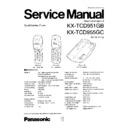
Read Panasonic KX-TCD951GB / KX-TCD955GC Service Manual online
KX-TCD951GB/KX-TCD955GC
2
WARNING
This service information is designed for experienced repair technicians only and is not designed for use by the general public.
It does not contain warnings or cautions to advise non-technical individuals of potential dangers in attempting to service a
product. Products powered by electricity should be serviced or repaired only by experienced professional technicians.
Any attempt to service or repair the product or products dealt with in this service information by anyone else could result in
serious injury or death.
When you mention the serial number, write down all 11 digits. The serial number may be found on the label affixed to the bottom
of the unit.
of the unit.
LOCATION OF CONTROLS ............................................. 3, 4
DISASSEMBLY INSTRUCTIONS ......................................... 5
SETTINGS ........................................................................ 6~8
OPERATION ................................................................... 9~10
SETTING THE RECEIVER VOLUME ................................. 11
CIRCUIT BOARD AND WIRING CONNECTION
DIAGRAM (BASE UNIT) ...... 13~14
SCHEMATIC DIAGRAM (BASE UNIT) ............................... 15
SCHEMATIC DIAGRAM (HANDSET) ................................. 16
CIRCUIT BOARD AND WIRING CONNECTION
DIAGRAM (HANDSET) .............. 17
BLOCK DIAGRAM RF UNIT (BASE UNIT) ........................ 18
CIRCUIT OPERATION (BASE UNIT) ................................. 18
BLOCK DIAGRAM BASEBAND SECTION
AND LINE INTERFACE (BASE UNIT) .................. 19~26
BLOCK DIAGRAM RF SECTION (HANDSET) ................... 27
BLOCK DIAGRAM BASEBAND SECTION
(HANDSET) ................................ 28
TABLE OF CONTENTS
CIRCUIT OPERATION (HANDSET) ............................... 29~34
ADJUSTMENT (BASE UNIT) ................................................ 35
ADJUSTMENT (HANDSET) .................................................. 36
CHECK PROCEDURE (BASE UNIT) .............................. 37~39
CHECK PROCEDURE (HANDSET) ................................ 40, 41
TROUBLESHOOTING GUIDE ........................................ 42~50
EEPROM LAYOUT (BASE UNIT) ................................... 51~58
EEPROM LAYOUT (HANDSET) ..................................... 59~65
CABINET AND ELECTRICAL
PARTS LOCATION (BASE UNIT) ................................. 66
CABINET AND ELECTRICAL
PARTS LOCATION (HANDSET) ................................... 67
ACCESSORIES AND PACKING MATERIALS ...................... 68
REPLACEMENT PARTS LIST (BASE UNIT) .................. 69~71
REPLASEMENT PARTS LIST (HANDSET) .................... 72~74
FOR SERVICE TECHNICIANS
ICs and LSIs are vulnerable to static electricity.
When repairing, the following precautions will help prevent recurring malfunctions.
1. Cover plastic parts boxes with aluminum foil.
2. Ground the soldering irons.
3. Use a conductive mat on worktable.
4. Do not grasp IC or LSI pins with bare fingers.
When repairing, the following precautions will help prevent recurring malfunctions.
1. Cover plastic parts boxes with aluminum foil.
2. Ground the soldering irons.
3. Use a conductive mat on worktable.
4. Do not grasp IC or LSI pins with bare fingers.
KX-TCD951GB/KX-TCD955GC
3
1
ABC
2
DEF
3
G HI
4
J KL
5
MNO
6
PQRS
7
TUV
8
0
WXYZ
9
R
F
C
INT’
OK
OK
Display
Talk Button
Function Button
Recall Button
Charge Contacts
F
Tone Button
Intercom Button
Arrow Key
( , OK , , )
( , OK , , )
Cancel Button
Power Button
I N T
C
R
LOCATION OF CONTROLS
BASE UNIT
HANDSET
Charge Contacts
Page Button
In Use Indicator ( )
Charge Indicator ( )
CALLER ID Indicator ( )
(KX-TCD955GB only)
(KX-TCD955GB only)
Antenna
CALLER ID
Fig. 1
Fig. 2
(KX-TCD951GB)
(KX-TCD955GC)
1
ABC
2
DEF
3
G HI
4
J KL
5
MNO
6
PQRS
7
TUV
8
0
WXYZ
9
R
INT’
OK
C
Display
Talk Button
Cancel Button
Program Button
Recall Button
Charge Contacts
Tone Button
Intercom Button
Redial/Pause
Button
Button
OK Button
Power Button
I N T
O K
R
Arrow Key
( , OK , , )
( , OK , , )
C
KX-TCD951GB/KX-TCD955GC
4
Icons:
The in range icon indicates that the handset is in range of the base unit.
It flashes when the handset is out of range.
It flashes when the handset is out of range.
The handset is out of range. Move closer to the base unit.
The handset is being paged from another unit.
The page/intercom icon is displayed when paging or using the intercom.
It flashes when another unit pages the handset.
It flashes when another unit pages the handset.
The talk icon is displayed when making or answering calls. It flashes when an outside call is
being received.
being received.
An outside call is received.
The direct call icon is displayed when this mode is turned on. (KX-TCD951GB only)
The call prohibition icon is displayed when this mode is turned on.
The program icon indicated that the unit is in the programming mode. (KX-TCD951GB only.)
The Caller ID icon is displayed when viewing the Caller List or "Private ring" is set in the
phonebook. (KX-TCD955GC Only)
phonebook. (KX-TCD955GC Only)
The phonebook icon is displayed when storing or viewing the phonebook items.
(KX-TCD955GC Only)
(KX-TCD955GC Only)
The present battery strength is displayed.
(Flashing)
(Flashing)
(Flashing)
(KX-TCD955GC)
(KX-TCD951GB)
A B C D E F G H I a b c d e f g
1234567890123456
Characters:
is pressed while dialing.
is pressed while dialing.
is pressed while dialing.
is pressed while dialing.
“Pause” is selected while dialing.
is pressed while dialing.
(KX-TCD951GB)
(KX-TCD955GC)
P
F


