Read Panasonic PT-TW371R (serv.man3) Service Manual online
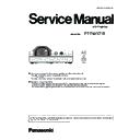
Model No.
PT-TW371R
LCD Projector
ORDER NO. VED1812723CE
Rev.-1 (2019-02)
For the block diagrams, schematic diagrams and parts list, refer to each separated booklet "Block and Schematic
diagrams" and "Parts List" respectively.
This manual is common to the models regardless of suffixes of the Model No..
The suffix of model No. shows the destination as below.
- "T" for Taiwan
The model which does not have the destination suffix is for global model in common.
Illustrations in this service manual
Illustrations of the projector, menu screen (OSD) , and other parts may vary from the actual product.
Illustrations of the projector with the power cord attached are only examples.
The shape of the supplied power cords varies depending on the country where you purchased the product.
2
PREFACE
<TW371R>
CAUTION:
About lead free solder (PbF)
This projector is using the P.C.Board which applies lead free solder.
Use lead free solder in servicing from the standpoint of antipollution for the global environment.
Notes:
• Lead free solder: Sn-Ag-Cu (tin, silver and copper) has a higher melting point (approx. 217°C) than standard solder Typically
the melting point is 30~40 °C higher. When servicing, use a high temperature soldering iron with temperature limitation
function and set it to 370 ± 10 °C.
• Be precautious about lead free solder. Sn-Ag-Cu (tin, silver and copper) will tend to splash when heated too high (approx.
600°C or higher).
• Use lead free solder for the P.C.Board (specified on it as “PbF”) which uses lead free solder. (When you unavoidably use
lead solder, use lead solder after removing lead free solder. Or be sure to heat the lead free solder until it melts completely,
before applying lead solder.)
• After solder to double layered P.C.Boards, check the component side for excess solder which may flow onto the opposite side.
About the identification of the lead free solder P.C.Board.
For the P.C.Board which applies lead free solder, the symbol as shown in the figure below is printed or stamped on the surface
or the back of P.C.Board.
PbF
WARNING:
This equipment has been tested and found to comply with the limits for a Class B digital device, pursuant to Part 15 of the FCC Rules.
These limits are designed to provide reasonable protection against harmful interference in a residential installation. This equipment
generates, uses and can radiate radio frequency energy and, if not installed and used in accordance with the instructions, may cause
harmful interference to radio communications. However, there is no guarantee that interference will not occur in a particular installation.
If this equipment does cause harmful interference to radio or television reception, which can be determined by turning the equipment off
and on, the user is encouraged to try to correct the interference by one of the following measures:
f
Reorient or relocate the receiving antenna.
f
Increase the separation between the equipment and receiver.
f
Connect the equipment into an outlet on a circuit different from that to which the receiver is connected.
f
Consult the dealer or an experienced radio/BD technician for help.
The user may find the booklet “Something About Interference” available from FCC local regional offices helpful.
FCC Warning:
To assure continued FCC emission limit compliance, follow the attached installation instructions. This includes using the provided power
cord and shielded interface cables when connecting to computer or peripheral devices. Also, any unauthorized changes or modifications
to this equipment could void the user’s authority to operate this device.
CAUTION:
Any unauthorized changes or modifications to this equipment will void the user’s authority to operate this device.
There are special components used in this equipment which are important for safety. These parts are marked by 7 in the schematic
diagram, circuit board diagrams, exploded views and replacement parts list. It is essential that these critical parts should be replaced
with manufacturer’s specified parts to prevent shock, fire, or other hazards. Do not modify the original design without permission of
manufacturer.
IMPORTANT SAFETY NOTICE
The service technician is required to read and follow the “Safety Precautions” and “Important Safety Notice” in this service manual.
Le technicien d'entretien doit lire et suivre les «Précautions de sécurité» et «Avis important de sécurité» dans ce manuel d'entretien.
7
WARNING
This service information is designed for experienced repair technicians only and is not designed for used by the general
public. It does not contain warnings or cautions to advise non-technical individuals of potential dangers in attempting to service a
product. Products powered by electricity should be serviced or repaired only by experienced professional technicians. Any attempt
to service or repair the product or products dealt with in this service information by anyone else could result in serious injury or
death.
7
AVERTISSEMENT
Ce document d'entretien est destiné aux techniciens d'entretien expérimentés uniquement et n'est pas conçu pour une utilisation
par le grand public. Il ne contient pas des avertissements ou des mises en garde pour aviser les non-techniciens des dangers
potentiels lorsqu'ils tentent de réparer un produit. Les appareils alimentés par l'électricité doivent être révisés ou réparés unique-
ment par des techniciens professionnels expérimentés. Toute tentative d'entretenir ou de réparer le ou les produits traités dans ce
document d'entretien par autrui peut entraîner des blessures graves ou la mort.
WARNING : Use UV Radiation eye and skin protection during servicing.
AVERTISSEMENT : Utilisez UV lumière oeil dioprotection et la protection de la peau lors de l'entretien.
3
PREFACE
<TW371R>
Notes on repairing
f
In case of fuse opening inside the projector, Do not turn the projector on just replacing the fuse with new one because there
might be a possibility to have smoking or firing hazard. Turn it on after solving the main cause of fuse opening.
f
After repairing, confirm that the projector operates correctly.
f
Pay attention to handle the projector as customer's personal settings have been remaining inside the projector.
Cautions when transporting
f
When transporting the projector, hold it securely by its bottom and avoid excessive vibration and impacts. Doing so may
damage the internal parts and result in malfunctions.
f
Do not transport the projector with the adjustable feet extended. Doing so may damage the adjustable feet.
f
Do not move or transport the projector with the wireless module (Model No.: ET-WML100) of the optional accessories
attached. Doing so may damage the wireless module.
Cautions when installing
r
Do not set up the projector outdoors.
The projector is designed for indoor use only.
r
Do not set up the projector in the following locations.
f
Places where vibration and impacts occur such as in a car or vehicle: Doing so may cause damage to internal components
or malfunction.
f
Locations near the sea or areas affected by corrosive gas: Corrosion may damage internal components or cause the
projector to malfunction.
f
Near the exhaust of an air conditioner: Depending on the conditions of use, the screen may fluctuate in rare cases due to
the heated air from the air exhaust port or the hot or cooled air. Make sure that the exhaust from the projector or other
equipment, or the air from the air conditioner does not blow toward the front of the projector.
f
Places with sharp temperature fluctuations such as near lights (studio lamps): Doing so may shorten the life of the lamp, or
result in deformation of the outer case due to heat, which may cause malfunctions.
Follow the operating environment temperature of the projector.
f
Near high-voltage power lines or near motors: Doing so may interfere with the operation of the projector.
r
Ask a qualified technician or your dealer for the installation work such as installing to a ceiling.
To ensure projector performance and safety, ask a qualified technician or your dealer when installing to a ceiling or in a high
place.
r
Focus adjustment
The projection lens is thermally affected by the light from the light source, making the focus unstable in the period just after
switching on the power. It is recommended that the images be projected continuously for at least 30 minutes before the focus
is adjusted.
r
When using the projector in the elevation of below 700 m (2 297'), make sure [High land] is set to [Off].
Failure to do so may shorten the life of the internal parts and result in malfunctions.
r
When using the projector in the elevation of above 700 m (2 297') and below 1 400 m (4 593'), make sure
[High land] is set to [On 1].
Failure to do so may shorten the life of the internal parts and result in malfunctions.
r
When using the projector in the elevation of above 1 400 m (4 593') and below 2 700 m (8 858'), make sure
[High land] is set to [On 2].
Failure to do so may shorten the life of the internal parts and result in malfunctions.
r
Do not install the projector at elevations of 2 700 m (8 858') or higher above sea level.
Failure to do so may shorten the life of the internal parts and result in malfunctions.
r
Do not tilt the projector or place it on its side.
Do not tilt the projector body more than approximately ±30° vertically or ±15° horizontally. Over tilting may result in shortening
the life of the components.
The angle that can be corrected through [Expand] menu → [Keystone] → [H/V Keystone] is within ±15°. If the vertical tilt of the
projector with respect to the screen surface exceeds 15°, vertical trapezoidal distortion may not be corrected.
4
PREFACE
<TW371R>
r
Cautions when setting the projectors
f
Use the adjustable foot only for adjusting the angle. Using them for other purposes may damage the projector.
f
Do not stack the projectors.
f
Do not use the projector supporting it by the top.
f
Do not block the ventilation ports (intake and exhaust) of the projector.
f
Avoid heating and cooling air from the air conditioning system directly blow to the ventilation ports (intake and exhaust) of the
projector.
f
Do not install the projector in a confined space.
When placing the projector in a confined space, a ventilation and/or air conditioning system is required. Exhaust heat may
accumulate when the ventilation is not enough, triggering the protection circuit of the projector.
Within 15°
Within 15°
Within 30°
Within 30°


