Read Panasonic DP-150 Service Manual online
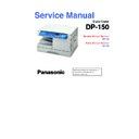
Service Manual Section
DP-150
Parts Manual Section
DP-150
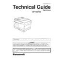
Service Manual
Digital Copier
DP-150
Table of Contents
General
Description
Mechanism
Maintenance
PCB Connector and
Signal Information
Troubleshooting
Installation
WARNING
Section I General Description
1.1
Specifications ................................................................................
1-1
1.2
Features .........................................................................................
1-3
1.3
New Functions ...............................................................................
1-3
1.4
Systems .........................................................................................
1-4
1.5
Control Panel .................................................................................
1-5
1.6
Component Location .....................................................................
1-6
1. Outer View .................................................................................
1-6
2. Inner View ..................................................................................
1-6
3. Fan/ Motor Location ...................................................................
1-7
4. Sensor Location .........................................................................
1-7
5. Solenoid/Switch Location ..........................................................
1-8
6. PCB Location .............................................................................
1-8
1.7
Copy Process ................................................................................
1-9
1.8
Precautions for Consumables .....................................................
1-10
Section II Mechanism
2.1
Main Drive ......................................................................................
2-1
2.2
Operations .....................................................................................
2-2
1. Sheet Bypass ............................................................................
2-2
2. Paper Feed Unit ........................................................................
2-4
3. Toner Cartridge .........................................................................
2-6
4. Fuser Unit ..................................................................................
2-9
5. Optics Unit ...............................................................................
2-12
6. Laser Unit ................................................................................
2-15
DP-150
Section III Maintenance
3.1
Precautions for Preventive Maintenance Service ..........................
3-1
3.2
Maintenance Chart ........................................................................
3-3
3.3
Cleaning Method ...........................................................................
3-4
3.4
Disassembly and Re-assembly .....................................................
3-7
1. Sheet Bypass ............................................................................
3-8
2. Developer Unit/Drum unit ........................................................
3-13
3. Fuser Unit ................................................................................
3-18
4. Optics Unit ...............................................................................
3-21
5. Main Body ................................................................................
3-27
3.5
Adjustment ...................................................................................
3-28
1. Exposure Adjustment ..............................................................
3-29
2. Skew/Side position Adjustment (Printer unit) ..........................
3-30
3. Skew/Lead edge position Adjustment (Scanner unit) ..............
3-31
4. Void Registration Adjustment ..................................................
3-31
3.6
Updating the Firmware ................................................................
3-32
Section IV PCB Connector and Signal Information
4.1
Glossary of Electrical Abbreviations ..............................................
4-1
4.2
Main CPU PCB ..............................................................................
4-3
4.3
LVPS PCB ...................................................................................
4-13
Section V Troubleshooting
5.1
Service Mode .................................................................................
5-1
1. Service Mode Functions ............................................................
5-1
2. F4 Mode : Input/Output Check ..................................................
5-3
3. F5 Mode : Copier Function Programming .................................
5-5
4. F6 Mode : Adjustment and Programming ..................................
5-6
5. F7 Mode : Electronic Counter ....................................................
5-8
6. F8 Mode : Copier Operating Adjustment ...................................
5-9
7. F9 Mode : Service Mode .........................................................
5-10
5.2
Self-diagnostics/Machine Malfunctions .......................................
5-11
1. User Error :U code ...................................................................
5-11
2. Paper Jam : J code ..................................................................
5-12
3. Machine Error : E code ............................................................
5-13
Schematic Diagram
WARNING
This service information is designed for experienced repair technicians only and
is not designed for use by the general public.
It does not contain warnings or cautions to advise non-technical individuals of
potential dangers in attempting to service a product.
Products powered by electricity should be serviced or repaired only by experienced
is not designed for use by the general public.
It does not contain warnings or cautions to advise non-technical individuals of
potential dangers in attempting to service a product.
Products powered by electricity should be serviced or repaired only by experienced
professional technicians. Any attempt to service or repair the product or products
dealt with in this service information by anyone else could result serious injury or
death.
dealt with in this service information by anyone else could result serious injury or
death.
For U.S.A
This equipment has been tested and found to comply with the limits for a Class A
digital device, pursuant to part 15 of the FCC Rules. These limits are designed to
provide reasonable protection against harmful interference when the equipment
digital device, pursuant to part 15 of the FCC Rules. These limits are designed to
provide reasonable protection against harmful interference when the equipment
is operated in a commercial environment. This equipment generates, uses, and
can radiate radio frequency energy and, if not installed and used in accordance
with the instruction manual, may cause harmful interference to radio
communications. Operation of this equipment on a residential area is likely to
cause harmful interference in which case the user will be required to correct the
interference at his/her own expense.
Any unauthorized changes or modifications to this equipment would void the users
authority to operate this device.
authority to operate this device.
For U.S.A
This manual was developed and is supplied to authorized servicing dealers by
Panasonic Document Imaging Co. for the sole purpose of providing information
necessary for the equipment’s proper support. It is intended that this information
Panasonic Document Imaging Co. for the sole purpose of providing information
necessary for the equipment’s proper support. It is intended that this information
be confidential and may not reproduced without prior written consent from
Panasonic Document imaging Co. Panasonic Document imaging Co. reserves
the right to change any information enclosed herein without prior notification.
Panasonic Document imaging Co. Panasonic Document imaging Co. reserves
the right to change any information enclosed herein without prior notification.
This manual was developed and is supplied to authorized servicing dealers by
Panasonic Co. for the sole purpose of providing information necessary for the
Panasonic Co. for the sole purpose of providing information necessary for the
equipment’s proper support. It is intended that this information be confidential
and may not be reproduced without prior written consent from Panasonic Co.
Panasonic Co. reserves the right to change any information enclosed herein without
prior notification.
and may not be reproduced without prior written consent from Panasonic Co.
Panasonic Co. reserves the right to change any information enclosed herein without
prior notification.


