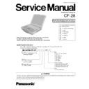
Read Panasonic CF-28 Service Manual online
ORDER NO. CPD0102001C0
Notebook Computer
Model Number Reference
This is the Service Manual for
the following areas.
the following areas.
M ...for U.S.A. and Canada
E ...for U.K.
G ...for Germany
F ...for France
S ...for Sweden
T ...for Italy
P ...for Spain
The models in the CF-28 series are numbered in accordance with the types of the CPU, LCD
and HDD etc. featured by the product.
and HDD etc. featured by the product.
WARNING
Model No.CF-28 Z
LCD type
C: for 13.3" TFT Color
with Touch Screen
HDD type / RAM size
F: 20 GB / 128 MB
Area
M: for U.S.A. and Canada
E: for U.K.
G: for Germany
F: for France
S: for Sweden
T: for Italy
P: for Spain
E: for U.K.
G: for Germany
F: for France
S: for Sweden
T: for Italy
P: for Spain
Drive
A: Floppy Disk drive
CPU type
M: for Intel
®
Mobile Pentium
®
III
Processor 600 MHz
Operating System
C: Microsoft
®
Windows NT
®
D: Microsoft
®
Windows
®
2000
E: Microsoft
®
Windows
®
98
CF-28
- 2 -
LASER SAFETY INFORMATION
For U.S.A.
Class 1 LASER-Product
This product is certified to comply with DHHS Rules 21 CFR Subchapter J.
This product complies with European Standard EN60825 (or IEC Publication 825).
This product complies with European Standard EN60825 (or IEC Publication 825).
For all areas
This equipment is classified as a class 1 level LASER product and there is no hazardous LASER radiation.
This equipment is classified as a class 1 level LASER product and there is no hazardous LASER radiation.
Caution:
(1) Use of controls or adjustments or performance of procedures other than those specified herein may result in
(1) Use of controls or adjustments or performance of procedures other than those specified herein may result in
hazardous radiation exposure.
(2) The drive is designed to be incorporated into a computer-based system or unit which has an enclosing cover.
It should never be used as a stand alone drive.
Danger:
The serviceman should not remove the cover of drive unit and should not service because the drive unit is a non-
serviceable part.
The serviceman should not remove the cover of drive unit and should not service because the drive unit is a non-
serviceable part.
• Unplug the AC power cord to the equipment before opening the top cover of the drive.
• When the power switch it on, do not place your eyes close to the front panel door to look into the interior of the unit.
• When the power switch it on, do not place your eyes close to the front panel door to look into the interior of the unit.
LASER Specification
Class 1 level LASER Product
Wave Length : DVD 658
Wave Length : DVD 658
±
8 nm
CD
775 ~ 815 nm
Laser safety information is appropriate only when drive with laser is installed.
CAUTION
Danger of explosion if battery is incorrectly replaced.
Replace only with the same or equivalent type recommended by the equipment manufacture.
Discard used batteries according to the manufacturer's instructions.
Replace only with the same or equivalent type recommended by the equipment manufacture.
Discard used batteries according to the manufacturer's instructions.
Vorsicht!
Explosionsgefahr bei unsachgemäßem Austausch der Batterie. Ersatz nur durch denselben order einen vom
Hersteller empfohlenen ähnlichen Typ. Entsorgung gebrauchter Batterien nach Angaben des Herstellers.
Explosionsgefahr bei unsachgemäßem Austausch der Batterie. Ersatz nur durch denselben order einen vom
Hersteller empfohlenen ähnlichen Typ. Entsorgung gebrauchter Batterien nach Angaben des Herstellers.
LITHIUMBATTERIES
ATTENTION: IL Y A DANGER D'EXPLOSION S' IL Y A REMPLACEMENT INCORRECT DE LA PILE.
REMPLACER UNIQUEMENT AVEC UNE PILE DU MÈME TYPE OU D'UN TYPE RECOMMANDÉ PAR LE
CONSTRUCTEUR. METTRE AU RÉBUT LES PILES USAGÉES CONFORMÉMENT AUX INSTRUCTIONS DU
FABRICANT.
REMPLACER UNIQUEMENT AVEC UNE PILE DU MÈME TYPE OU D'UN TYPE RECOMMANDÉ PAR LE
CONSTRUCTEUR. METTRE AU RÉBUT LES PILES USAGÉES CONFORMÉMENT AUX INSTRUCTIONS DU
FABRICANT.
PILE AU LITHIUM
LITHIUM BATTERY
-
3 -
Contents
1. Specifications
.......................................................
2. Name and Functions of Parts
..........................
3. Technical information
........................................
3.1. System Overview.............................................
3.2. System Memory Map.......................................
3.3. I/O Address Map..............................................
3.2. System Memory Map.......................................
3.3. I/O Address Map..............................................
4. Diagnosis Procedure
..........................................
4.1. Basic Procedures.............................................
4.2. Power-On Self Test (Boot Check)....................
4.3. List of Error Codes...........................................
4.4. Diagnosis Map..................................................
4.2. Power-On Self Test (Boot Check)....................
4.3. List of Error Codes...........................................
4.4. Diagnosis Map..................................................
5. Diagnostic Test
....................................................
5.1. Diagnostic Test Procedure...............................
5.2. Error Message..................................................
5.2. Error Message..................................................
6. Disassembly/Reassembly
.................................
6.1. Removing the Battery Pack..............................
6.2. Removing the HDD Unit...................................
6.3. Removing the Unit
6.2. Removing the HDD Unit...................................
6.3. Removing the Unit
from inside the Multimedia Pocket..................
6.4. Removing the Keyboard.................................
6.5. Removing the Display Unit...............................
6.6. Removing the RAM Card.................................
6.7. Removing the Lower Casing
6.5. Removing the Display Unit...............................
6.6. Removing the RAM Card.................................
6.7. Removing the Lower Casing
and the Handle............................................
6.8. Removing the I/O Board.................................
6.9. Removing the Modem Board......................
6.10. Removing the MP Connection Unit..................
6.11. Removing the Main PCB.................................
6.12. Removing the Touch Pad Unit......................
6.13. Removing the PCMCIA CN
6.9. Removing the Modem Board......................
6.10. Removing the MP Connection Unit..................
6.11. Removing the Main PCB.................................
6.12. Removing the Touch Pad Unit......................
6.13. Removing the PCMCIA CN
(PC Card Slot)..............................................
6.14. Removing RTC Battery....................................
6.15. Removing the INVERTER,
6.15. Removing the INVERTER,
the Touch Screen PCB
and TS13 PCB.................................................
and TS13 PCB.................................................
6.16. Removing the LCD
and the Touch Screen.....................................
7. Wiring Connection Diagram
.............................
8. Exploded Views
.................................................
9. Replacement Parts List
...................................
10. Schematic Diagrams
........................................
MAIN 1 CPU.............................................................
MAIN 2 CPU.............................................................
MAIN 3 VC1.6/1.35, VCT, VC25...............................
MAIN 4 CORE...........................................................
MAIN 5 CORE...........................................................
MAIN 6 CLOCK.........................................................
MAIN 7 ONBOARD MEMORY..................................
MAIN 8 EXT. MEMORY CON...................................
MAIN 9 PIIX4, USB...................................................
MAIN 10 PIIX4, USB.................................................
MAIN 11 HDD...........................................................
MAIN 12 MP,TESTER CN........................................
MAIN 13 VGA...........................................................
MAIN 14 LCD&CRT I/F,LVDS..................................
MAIN 15 PCMCIA CONT. .......................................
MAIN 16 PCMCIA I/F................................................
MAIN 17 SuperI/O-1, COMSEL GA..........................
MAIN 18 SuperI/O-2, IrDA BUF................................
MAIN 19 KBC, K/B PAD CN.....................................
MAIN 20 SOUND IC.................................................
MAIN 21 Power Amp, MIC,SPK,H-PHONE..............
MAIN 22 Ext.IO I/F (FFC-CONN)LAN CN................
MAIN 23 LED............................................................
MAIN 24 Mini PCI.....................................................
MAIN 25 BIOS,VD12................................................
MAIN 26 VC3,VB3,VC5,VB5,Reset..........................
MAIN 27 EC,LID.......................................................
MAIN 28 VA3,VA5....................................................
MAIN 29 DC-IN,VM1 PWR SW................................
MAIN 30 Charger BAT CN........................................
MAIN 31 Wireless Module CONN. EXT_ROM.........
MAIN 32 GCL............................................................
MAIN 33 Smart Card I/F...........................................
MAIN 34 I/O Expander..............................................
MAIN 35 PCMCIA-3..................................................
MAIN 36 PCMCIA-3 CONN......................................
SUB1 I/O...................................................................
SUB2 I/O...................................................................
SUB3 I/O...................................................................
SUB4 MP CN, FDD CN............................................
SUB5 IR....................................................................
SUB6 Main Battery...................................................
SUB7 RJ MODEM....................................................
SUB8 TS13...............................................................
11. Printed Circuit Board
.......................................
11.1. Main PCB <Top View>.....................................
11.2. Main PCB <Bottom View>................................
11.3. FDD PCB <Top View>.....................................
11.4. FDD PCB <Bottom View>................................
11.5. I/O PCB <Top View>........................................
11.6. I/O PCB <Bottom View>...................................
11.7. Battery PCB......................................................
11.8. IR PCB.............................................................
11.9. RJ PCB.............................................................
11.10. TS13 PCB.......................................................
1-1, 1-2
2-1, 2-2
3-1~3-4
2-1, 2-2
3-1~3-4
3-1, 3-2
3-3
3-4
3-3
3-4
4-1~4-12
4-1
4-2
4-3, 4-4
4-5~4-12
4-2
4-3, 4-4
4-5~4-12
5-1~5-15
5-1~5-9
5-10~5-15
5-10~5-15
6-1~6-5
6-1
6-1
6-1
6-2
6-2
6-3
6-3
6-2
6-3
6-3
6-3
6-4
6-4
6-4
6-4
6-5
6-4
6-4
6-4
6-4
6-5
6-5
6-5
6-5
6-6
6-6
7-1
8-1~8-6
9-1~9-10
10-1~10-82
8-1~8-6
9-1~9-10
10-1~10-82
10-1, 10-2
10-3, 10-4
10-5, 10-6
10-7, 10-8
10-9, 10-10
10-11, 10-12
10-13, 10-14
10-15, 10-16
10-17, 10-18
10-19, 10-20
10-21, 10-22
10-23, 10-24
10-25, 10-26
10-3, 10-4
10-5, 10-6
10-7, 10-8
10-9, 10-10
10-11, 10-12
10-13, 10-14
10-15, 10-16
10-17, 10-18
10-19, 10-20
10-21, 10-22
10-23, 10-24
10-25, 10-26
10-27, 10-28
10-29, 10-30
10-31, 10-32
10-33, 10-34
10-35, 10-36
10-37, 10-38
10-39, 10-40
10-41, 10-42
10-43, 10-44
10-45, 10-46
10-47, 10-48
10-49, 10-50
10-51, 10-52
10-53, 10-54
10-55, 10-56
10-57, 10-58
10-59, 10-60
10-61, 10-62
10-63, 10-64
10-65
10-66
10-67
10-68, 10-69
10-70, 10-71
10-72, 10-73
10-74, 10-75
10-76, 10-77
10-78, 10-79
10-80
10-81
10-82
11-1~11-6
11-1, 11-2
11-3, 11-4
11-5
11-5
11-5
11-5
11-6
11-6
11-6
11-6
11-3, 11-4
11-5
11-5
11-5
11-5
11-6
11-6
11-6
11-6
-
4 -


