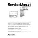
KX-TES824CA, KX-TEM824CA, KX-TE82461X, KX-TE82474X, KX-TE82480X, KX-TE82483X, KX-TE82491X, KX-TE82492X, KX-TE82493X, KX-A227X - Panasonic PBX Service Manual (repair manual)

kx-tes824ca, kx-tem824ca, kx-te82461x, kx-te82474x, kx-te82480x, kx-te82483x, kx-te82491x, kx-te82492x, kx-te82493x, kx-a227x service manual
Model
KX-TES824CA KX-TEM824CA KX-TE82461X KX-TE82474X KX-TE82480X KX-TE82483X KX-TE82491X KX-TE82492X KX-TE82493X KX-A227X
Pages
127
Size
10.86 MB
Type
PDF
Document
Service Manual
Brand
Device
PBX / ADVANCED HYBRID SYSTEM
File
kx-tes824ca-kx-tem824ca-kx-te82461x-kx-te82474x-kx.pdf
Date

Read Panasonic KX-TES824CA / KX-TEM824CA / KX-TE82461X / KX-TE82474X / KX-TE82480X / KX-TE82483X / KX-TE82491X / KX-TE82492X / KX-TE82493X / KX-A227X Service Manual online

ORDER NO. KMS0804482CE
Advanced Hybrid System
Model No.
KX-TES824CA
KX-TEM824CA
KX-TE82461X
KX-TE82474X
KX-TE82480X
KX-TE82483X
KX-TE82491X
KX-TE82492X
KX-TE82493X
KX-A227X
(for Kazakhstan, Uzbekistan, Kyrgyzstan, Tajikistan
and Turkmenistan)
2
KX-TES824CA/KX-TEM824CA
TABLE OF CONTENTS
PAGE
PAGE
1 Safety Precautions -----------------------------------------------5
1.1. For Service Technicians  ---------------------------------5
1.2. Insulation Resistance Test -------------------------------5
2 Warning --------------------------------------------------------------6
2.1. Battery Caution ---------------------------------------------6
2.2. Caution--------------------------------------------------------6
2.3. About Lead Free Solder (PbF: Pb free) --------------6
3 Specifications ------------------------------------------------------7
3.1. General Description ---------------------------------------7
3.2. Characteristics ----------------------------------------------7
4 Technical Descriptions------------------------------------------8
4.1. System Block Diagram------------------------------------8
4.2. Power Block Diagram -------------------------------------9
4.3. Main Block Diagram  --------------------------------------9
4.4. Option Block Diagram (KX-TEM824CA Only) ---- 10
4.5. Power Supply Unit Block Diagram------------------- 10
4.6. Explanation of Block Diagram (Main Unit) --------- 11
4.7. Circuit Operation (Power Supply Circuit)----------- 13
4.8. CO Interface Circuit-------------------------------------- 14
4.9. Cross Point Switch Circuit ----------------------------- 18
4.10. Intercom Circuit ------------------------------------------- 20
4.11. Power Failure Through Call Switching Circuit ---- 21
4.12. DATA Communication Circuit ------------------------- 22
4.13. Control Circuit --------------------------------------------- 23
4.14. TONE Generator Circuit -------------------------------- 24
4.15. DTMF Generator Circuit-------------------------------- 25
4.16. DTMF Receiver Circuit---------------------------------- 26
4.17. INT CALL ID Interface Circuit ------------------------- 27
4.18. MODEM Interface Circuit------------------------------- 27
4.19. USB Interface Circuit------------------------------------ 28
4.20. OGM Interface Circuit----------------------------------- 28
4.21. Ringing Signal Generator Circuit--------------------- 29
4.22. SMDR Interface Circuit --------------------------------- 29
4.23. DOORPHONE Card Interface (KX-
TE82461X)------------------------------------------------- 30
4.24. OGM Card Interface (KX-TE82491X)--------------- 30
4.25. BUILT in Voice Message Card Interface (KX-
TE82492X)------------------------------------------------- 31
4.26. CALL ID Card Interface (KX-TE82493X)----------- 31
5 Location of Controls and Components------------------ 32
5.1. Name and Locations ------------------------------------ 32
6 Installation Instructions--------------------------------------- 32
6.1. Connection ------------------------------------------------ 32
6.2. System Capacity ----------------------------------------- 33
6.3. System Overview ---------------------------------------- 33
7 Troubleshooting Guide --------------------------------------- 35
7.1. No Operation (Check Power Supply Board,
Main Board) ----------------------------------------------- 35
7.2. No Dial TONE (Main Board) -------------------------- 36
7.3. Cannot Dial (Main Board) ----------------------------- 37
7.4. Cannot Call Extension (Main Board) --------------- 38
7.5. Cannot Use Proprietary Telephone (Main
Board) ------------------------------------------------------ 38
7.6. Cannot Receive Incoming Call (Main Board)----- 38
7.7. Cannot Send DTMF Dialing (Main Board) -------- 39
7.8. Cannot Receive Call Dial Tone (Main Board) ---- 39
7.9. Cannot Send a Hold On Music (Main Board)----- 40
7.10. No Dial Tone (Option Board KX-TEM824CA
Only) -------------------------------------------------------- 40
7.11. Cannot Dial (Option Board KX-TEM824CA
Only) -------------------------------------------------------- 41
7.12. Cannot Call Extension (Option Board KX-
TEM824CA Only)---------------------------------------- 41
7.13. Cannot Use Proprietary Telephone (Option
Board KX-TEM824CA Only) -------------------------- 42
7.14. Cannot Receive Incoming Call (Option Board
KX-TEM824CA Only) ----------------------------------- 42
7.15. Cannot Send DTMF Dialing (Option Board
KX-TEM824CA Only) ----------------------------------- 42
7.16. Cannot Receive Call Dial Tone (Option Board
KX-TEM824CA Only) ----------------------------------- 43
7.17. Cannot Send a Hold On Music (Option Board
KX-TEM824CA Only) ----------------------------------- 43
8 Service Fixture & Tools--------------------------------------- 44
9 Disassembly and Assembly Instructions 
-------------- 45
10 Maintenance------------------------------------------------------ 48
10.1. Terminal Guide of the ICs Transistors and
Diodes ------------------------------------------------------ 48
10.2. How To Replace a Flat Package IC----------------- 49
10.3. Memo ------------------------------------------------------- 50
11 Schematic Diagram -------------------------------------------- 51
11.1. Block Diagram -------------------------------------------- 51
11.2. Main No.1 (Extention A-D Block) -------------------- 52
11.3. Main No.2 (Extention E-H Block) -------------------- 56
3
     KX-TES824CA/KX-TEM824CA
11.4. Main No.3 (CO Block) -----------------------------------60
11.5. Main No.4 (Cross-Point Block) ------------------------64
11.6. Main No.5 (ASIC, Memory Block) --------------------68
11.7. Option No.1 (KX-TEM824CA Only) ------------------72
11.8. Option No.2 (KX-TEM824CA Only) ------------------74
11.9. Option No.3 (KX-TEM824CA Only) ------------------76
11.10. Option No.4 (KX-TEM824CA Only) ------------------80
11.11. Power Supply----------------------------------------------82
11.12. Waveform---------------------------------------------------83
11.13. Memo --------------------------------------------------------85
12 Printed Circuit Board-------------------------------------------86
12.1. Main Board -------------------------------------------------86
12.2. Option Board (KX-TEM824CA Only) ----------------88
12.3. Power Supply----------------------------------------------90
13 Appendix Information of Schematic Diagram ---------91
14 Exploded View and Replacement Parts List 
-----------92
14.1. IC DATA -----------------------------------------------------92
14.2. Cabinet and Electric Parts------------------------------96
14.3. Accessories and Packing Materials------------------97
14.4. Replacement Parts List ---------------------------------98
15 KX-TE82461X (4-Port Doorphone Card) --------------- 117
15.1. DoorPhone/DoorOpener Card Block Diagram  - 118
15.2. Explanation of Block Diagram/Circuit
Operations------------------------------------------------ 120
15.3. Location of Optional Cards--------------------------- 120
15.4. Troubleshooting Guide -------------------------------- 121
15.5. Terminal Guide of the ICs Transistors and
Diodes ----------------------------------------------------- 122
15.6. Memo ------------------------------------------------------ 123
15.7. Schematic Diagram ------------------------------------ 124
15.8. Printed Circuit Board----------------------------------- 126
15.9. For the Schematic Diagram-------------------------- 126
15.10. IC Data ---------------------------------------------------- 127
15.11. Accessories and Packing Material ----------------- 128
15.12. Replacement Parts List ------------------------------- 129
16 KX-TE82474X (8-Port SLT Extension Card)----------- 132
16.1. Block Diagram------------------------------------------- 133
16.2. Explanation of Block Diagram ----------------------- 133
16.3. Location of Optional Cards--------------------------- 138
16.4. Troubleshooting Guide -------------------------------- 141
16.5. Terminal Guide of the ICs Transistors and
Diodes ----------------------------------------------------- 143
16.6. Schematic Diagram ------------------------------------ 144
16.7. Printed Circuit Board----------------------------------- 150
16.8. For the Schematic Diagram-------------------------- 151
16.9. IC Data ---------------------------------------------------- 152
16.10. Cabinet and Electrical Parts Location ------------- 154
16.11. ACCESSORIES AND PACKING MATERIALS-- 154
16.12. Replacement Parts List ------------------------------- 155
17 KX-TE82480X (2-Port Analogue CO Line and 8-
Port SLT Extension Card)----------------------------------- 159
17.1. Block Diagram------------------------------------------- 160
17.2. Explanation of Block Diagram ----------------------- 160
17.3. Circuit Operation---------------------------------------- 161
17.4. Location of Optional Cards--------------------------- 170
17.5. Troubleshooting Guide -------------------------------- 174
17.6. Terminal Guide of the ICs Transistors and
Diodes ----------------------------------------------------- 177
17.7. Schematic Diagram ------------------------------------ 178
17.8. Printed Circuit Board----------------------------------- 186
17.9. For the Schematic Diagram-------------------------- 187
17.10. IC Data---------------------------------------------------- 188
17.11. Cabinet and Electrical Parts Location------------- 190
17.12. Accessories and Packing Material----------------- 190
17.13. Replacement Parts List------------------------------- 191
18 KX-TE82483X (3-Port Analogue CO Line and 8-
Port Hybrid Extension Card) ------------------------------ 197
18.1. Block Diagram ------------------------------------------ 198
18.2. Explanation of Block Diagram ---------------------- 198
18.3. Circuit Operation --------------------------------------- 199
18.4. Location of Optional Cards -------------------------- 209
18.5. Troubleshooting Guide --------------------------------211
18.6. Terminal Guide of the ICs Transistors and
Diodes ---------------------------------------------------- 214
18.7. Memo ----------------------------------------------------- 215
18.8. Schematic Diagram------------------------------------ 215
18.9. Printed Circuit Board ---------------------------------- 224
18.10. For the Schematic Diagram ------------------------- 225
18.11. IC Data---------------------------------------------------- 226
18.12. Cabinet and Electrical Parts Location------------- 228
18.13. Accessories and Packing Material----------------- 228
18.14. Replacement Parts List------------------------------- 229
19 KX-TE82491X (Message Extension Card for
DISA/UCD OGMs) --------------------------------------------- 236
19.1. Block Diagram  ----------------------------------------- 237
19.2. Location of Optional Cards -------------------------- 238
19.3. Troubleshooting Guide ------------------------------- 239
19.4. Terminal Guide of the ICs Transistors and
Diodes ---------------------------------------------------- 239
19.5. Schematic Diagram------------------------------------ 240
19.6. Printed Circuit Board ---------------------------------- 242
19.7. For the Schematic Diagram ------------------------- 242
19.8. Accessories and Packing Material----------------- 243
19.9. Replacement Parts List------------------------------- 244
20 KX-TE82492X (2-Channel Voice Message Card)---- 245
20.1. Block Diagram  ----------------------------------------- 246
20.2. Circuit Operations-------------------------------------- 247
20.3. Location of Optional Cards -------------------------- 248
20.4. Troubleshooting Guide ------------------------------- 249
20.5. Terminal Guide of the ICs Transistors and
Diodes ---------------------------------------------------- 251
20.6. Schematic Diagram------------------------------------ 252
20.7. Printed Circuit Board ---------------------------------- 254
20.8. For the Schematic Diagram ------------------------- 255
20.9. IC Data---------------------------------------------------- 256
20.10. Accessories and Packing Material----------------- 257
20.11. Replacement Parts List------------------------------- 258
21 KX-TE82493X (3-Port Caller ID Card)------------------- 260
21.1. Block Diagram  ----------------------------------------- 261
21.2. Circuit Operations-------------------------------------- 261
21.3. Location of Optional Cards -------------------------- 262
21.4. Troubleshooting Guide ------------------------------- 263
21.5. Terminal Guide of the ICs Transistors and
Diodes ---------------------------------------------------- 264
21.6. Memo ----------------------------------------------------- 265
21.7. Schematic Diagram------------------------------------ 265
21.8. Printed Circuit Board ---------------------------------- 268
21.9. For the Schematic Diagram ------------------------- 269
21.10. IC Data---------------------------------------------------- 270
21.11. Accessories and Packing Material----------------- 271
21.12. Replacement Parts List------------------------------- 272
22 KX-A227X (Back-Up Battery Cable)--------------------- 274
4
KX-TES824CA/KX-TEM824CA
22.1. Accessories and Packing Material----------------- 275
22.2. Replacement Parts List ------------------------------- 276
Page of 127
Display

Download Panasonic KX-TES824CA / KX-TEM824CA / KX-TE82461X / KX-TE82474X / KX-TE82480X / KX-TE82483X / KX-TE82491X / KX-TE82492X / KX-TE82493X / KX-A227X Service Manual (Repair Manual)

Here you can read online and download Panasonic KX-TES824CA / KX-TEM824CA / KX-TE82461X / KX-TE82474X / KX-TE82480X / KX-TE82483X / KX-TE82491X / KX-TE82492X / KX-TE82493X / KX-A227X Service Manual in PDF. KX-TES824CA / KX-TEM824CA / KX-TE82461X / KX-TE82474X / KX-TE82480X / KX-TE82483X / KX-TE82491X / KX-TE82492X / KX-TE82493X / KX-A227X service manual will guide through the process and help you recover, restore, fix, disassemble and repair Panasonic KX-TES824CA / KX-TEM824CA / KX-TE82461X / KX-TE82474X / KX-TE82480X / KX-TE82483X / KX-TE82491X / KX-TE82492X / KX-TE82493X / KX-A227X PBX. Information contained in service manuals typically includes schematics / circuit diagrams, wiring diagrams, block diagrams, printed wiring boards, exploded views, parts list, disassembly / assembly, pcb.