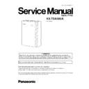
Read Panasonic KX-TDA30UA Service Manual online
2005 Panasonic Communications
KX-TDA30UA
(for Ukraine)
Hybrid IP-PBX
IMPORTANT INFORMATION ABOUT LEAD FREE, (PbF), SOLDERING
If lead free solder was used in the manufacture of this product the printed circuit boards will be marked PbF.
Standard leaded, (Pb), solder can be used as usual on boards without the PbF mark.
When this mark does appear please read and follow the special instructions described in this manual on the use of PbF and how
it might be permissible to use Pb solder during service and repair work.
it might be permissible to use Pb solder during service and repair work.
ORDER NO. KMS0506075CE
1
ABOUT LEAD FREE SOLDER (PbF: Pb free)
3
1.1.
SUGGESTED PbF SOLDER
3
1.2.
HOW TO RECOGNIZE THAT Pb FREE SOLDER IS
USED
4
2
FOR SERVICE TECHNICIANS
4
3
CAUTION
5
3.1.
NOTE
5
3.2.
SAFETY PRECAUTIONS
5
3.3.
INSULATION RESISTANCE TEST
5
3.4.
BATTERY CAUTION
5
3.5.
CAUTION
5
4
SPECIFICATIONS
6
4.1.
GENERAL DESCRIPTION
6
4.2.
CHARACTERISTICS
6
4.3.
SYSTEM CAPACITY
7
5
SYSTEM OVERVIEW
8
5.1.
SYSTEM COMPONENTS
8
5.2.
SYSTEM CONNECTION DIAGRAM
9
6
NAME AND LOCATIONS
11
7
CONNECTION
11
7.1.
Serial Interface Connection
11
7.2.
External Modem Connection
12
8
DISASSEMBLY INSTRUCTIONS
13
8.1.
DISASSEMBLY INSTRUCTION
13
9
OUTLINE
15
9.1.
GENERAL DESCRIPTION
15
9.2.
SYSTEM CONTROL
16
10 MAIN CARD CIRCUIT OPERATION
18
10.1. MAIN CARD
18
11 DIGITAL SUPER HYBRID PORTS CIRCUIT OPERATION
25
11.1. LINE-SYSTEM CIRCUIT
25
11.2. POWER SUPPLY CIRCUIT
30
12 TROUBLESHOOTING GUIDE
33
12.1. Introduction
33
12.2. POWER SUPPLY BOARD
34
12.3. System
40
12.4. PAGER/MOH
43
12.5. USB
48
12.6. Super hybrid ports
52
13 DIAGNOSIS
62
13.1. DIAGNOSIS FEATURES
62
13.2. READ THIS FIRST
64
14 IC DATA
66
14.1. IC101
66
14.2. IC102 (ASIC)
70
14.3. IC401 (CODEC)
75
14.4. IC302 (USB I/F)
76
14.5. IC303 (SD CARD I/F)
78
15 TERMINAL GUIDE OF ICS, TRANSISTORS AND DIODES
80
16 HOW TO REPLACE A FLAT PACKAGE IC
81
16.1. PREPARATION
81
16.2. PROCEDURE
81
16.3. REMOVING SOLDER FROM BETWEEN PINS
81
17 FIXTURESANDTOOLS
82
18 CABINET AND ELECTRICAL PARTS LOCATION
83
19 ACCESSORIES AND PACKING MATERIALS
84
20 REPLACEMENT PARTS LIST
85
20.1. CABINET AND ELECTRICAL PARTS
85
20.2. ACCESSORIES AND PACKING MATERIALS
85
20.3. MAIN BOARD PARTS
85
20.4. LED BOARD PARTS
96
20.5. FIXTURESANDTOOLS
96
21 FOR THE SCHEMATIC DIAGRAM
97
22 SCHEMATIC DIAGRAM
98
22.1. MAIN No.1 (CPU and ASIC Block)
98
22.2. MAIN No.2 (Memory Block)
102
22.3. MAIN No.3 (External Device Interface Block)
106
22.4. MAIN No.4 (Super Hybrid Port Block)
110
22.5. MAIN No.5 (Option Card Interface Block)
114
22.6. MAIN No.6 (Power Supply Block)
118
22.7. LED
122
22.8. WAVEFORM
123
23 PRINTED CIRCUIT BOARD
124
23.1. MAIN BOARD
124
23.2. LED BOARD
125
CONTENTS
Page
Page
2
KX-TDA30UA
1 ABOUT LEAD FREE SOLDER (PbF: Pb free)
Note:
In the information below, Pb, the symbol for lead in the periodic table of elements, will refer to standard solder or solder that
contains lead.
contains lead.
We will use PbF when discussing the lead free solder used in our manufacturing process which is made from Tin, (Sn), Silver,
(Ag), and Copper, (Cu).
(Ag), and Copper, (Cu).
This model, and others like it, manufactured using lead free solder will have PbF stamped on the PCB. For service and repair
work we suggest using the same type of solder although, with some precautions, standard Pb solder can also be used.
work we suggest using the same type of solder although, with some precautions, standard Pb solder can also be used.
Caution
·
PbF solder has a melting point that is 50° ~ 70° F, (30° ~ 40°C) higher than Pb solder. Please use a soldering iron with
temperature control and adjust it to 700° ± 20° F, (370° ± 10°C). In case of using high temperature soldering iron, please
be careful not to heat too long.
temperature control and adjust it to 700° ± 20° F, (370° ± 10°C). In case of using high temperature soldering iron, please
be careful not to heat too long.
·
PbF solder will tend to splash if it is heated much higher than its melting point, approximately 1100°F, (600°C).
·
If you must use Pb solder on a PCB manufactured using PbF solder, remove as much of the original PbF solder as possible
and be sure that any remaining is melted prior to applying the Pb solder.
and be sure that any remaining is melted prior to applying the Pb solder.
·
When applying PbF solder to double layered boards, please check the component side for excess which may flow onto the
opposite side (See figure, below).
opposite side (See figure, below).
1.1. SUGGESTED PbF SOLDER
There are several types of PbF solder available commercially. While this product is manufactured using Tin, Silver, and Copper,
(Sn+Ag+Cu), you can also use Tin and Copper, (Sn+Cu), or Tin, Zinc, and Bismuth, (Sn+Zn+Bi). Please check the
manufacturer’s specific instructions for the melting points of their products and any precautions for using their product with other
manufacturer’s specific instructions for the melting points of their products and any precautions for using their product with other
materials.
The following lead free (PbF) solder wire sizes are recommended for service of this product: 0.3mm, 0.6mm and 1.0mm.
3
KX-TDA30UA
1.2. HOW TO RECOGNIZE THAT Pb FREE SOLDER IS USED
2 FOR SERVICE TECHNICIANS
ICs and LSIs are vulnerable to static electricity.
When repairing, the following precautions will help prevent recurring malfunctions.
1. Cover the plastic parts boxes with aluminum foil.
2. Ground the soldering irons.
3. Use a conductive mat on the worktable.
4. Do not touch IC or LSI pins with bare fingers.
4
KX-TDA30UA

