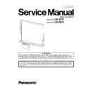
Read Panasonic UB-5335 / UB-5835 (serv.man2) Service Manual online
Order Number KM71204732CE
Category Number H19
Electronic Board
Model No.
UB-5335
Model No.
UB-5835
2
TABLE OF CONTENTS
PAGE
PAGE
1 GENERAL PRECAUTIONS -------------------------------------3
1.1. Safety Precautions-----------------------------------------3
1.2. Electrical Tests ----------------------------------------------4
1.3. Standard for Repair Service -----------------------------4
1.4. For Service Technicians ----------------------------------4
1.5. About Lead Free Solder (PbF: Pb free) --------------5
1.6. About RoHS -------------------------------------------------5
2 SPECIFICATIONS -------------------------------------------------6
2.1. Name Plate --------------------------------------------------6
2.2. Specifications -----------------------------------------------7
2.3. Abbreviations------------------------------------------------8
2.4. Trademarks --------------------------------------------------8
2.5. System Requirements ------------------------------------8
2.6. Exterior Dimensions ---------------------------------------9
3 COMPONENT IDENTIFICATION ---------------------------- 11
3.1. Main Unit --------------------------------------------------- 11
3.2. Control Panel---------------------------------------------- 12
3.2. Control Panel---------------------------------------------- 12
4 INSTALLATION--------------------------------------------------- 14
4.1. Requirements on Installation -------------------------- 14
4.2. Securing Space ------------------------------------------- 14
4.3. Checking Components---------------------------------- 15
4.4. Installation of Wall Hanging Fittings ----------------- 16
4.5. Attachment Operation (Board Attachment
4.2. Securing Space ------------------------------------------- 14
4.3. Checking Components---------------------------------- 15
4.4. Installation of Wall Hanging Fittings ----------------- 16
4.5. Attachment Operation (Board Attachment
Upper (A1), Board Attachment Lower (A2)) ------- 18
4.6. Panaboard Installation ---------------------------------- 20
4.7. Installing the Thermal Transfer Film----------------- 31
4.8. Operation Check after Installation ------------------- 34
4.7. Installing the Thermal Transfer Film----------------- 31
4.8. Operation Check after Installation ------------------- 34
5 SECTIONAL VIEW----------------------------------------------- 36
5.1. Screen Block ---------------------------------------------- 36
5.2. Printer Block ----------------------------------------------- 37
5.2. Printer Block ----------------------------------------------- 37
6 MECHANICAL FUNCTION ------------------------------------ 39
6.1. Screen Feed Mechanism ------------------------------ 39
6.2. Copy Mechanism----------------------------------------- 40
6.3. Printing Mechanism-------------------------------------- 41
6.4. Sensors ----------------------------------------------------- 43
6.2. Copy Mechanism----------------------------------------- 40
6.3. Printing Mechanism-------------------------------------- 41
6.4. Sensors ----------------------------------------------------- 43
7 MAINTENANCE -------------------------------------------------- 46
7.1. Maintenance List ----------------------------------------- 46
7.2. Cleaning or Replacing ---------------------------------- 46
7.2. Cleaning or Replacing ---------------------------------- 46
8 DISASSEMBLY INSTRUCTIONS---------------------------- 51
8.1. Disassembly Flowchart --------------------------------- 51
8.2. Screen Block ---------------------------------------------- 54
8.3. Printer Unit ------------------------------------------------- 68
8.4. Disassembly Parts when opening the Printer
8.2. Screen Block ---------------------------------------------- 54
8.3. Printer Unit ------------------------------------------------- 68
8.4. Disassembly Parts when opening the Printer
Door --------------------------------------------------------- 69
8.5. Disassembly Parts when removing the Paper
Cover and Paper Path Lower ------------------------- 73
8.6. Disassembly Parts when removing the Back
Plate --------------------------------------------------------- 78
9 Service Mode ----------------------------------------------------- 81
9.1. Operation--------------------------------------------------- 81
9.2. Contents ---------------------------------------------------- 82
9.2. Contents ---------------------------------------------------- 82
10 Adjustment -------------------------------------------------------- 85
10.1. Adjustment-1 (Image Sensor)------------------------- 85
10.2. Adjustment-2 (White/Black Slice Level
10.2. Adjustment-2 (White/Black Slice Level
Adjustment) ------------------------------------------------ 93
11 TROUBLESHOOTING ------------------------------------------ 95
11.1. Troubleshooting-1 (Error Code on the Control
Panel) ------------------------------------------------------- 95
11.2. Troubleshooting-2 (Problems regarding Image
Data) -------------------------------------------------------101
11.3. Troubleshooting-3 (Does Not Startup, etc.) ------104
11.4. Necessary Operation after Parts Replacement -105
11.4. Necessary Operation after Parts Replacement -105
12 CIRCUIT DESCRIPTION -------------------------------------106
12.1. Block Diagram-1 ----------------------------------------106
12.2. Block Diagram-2 (Boards)----------------------------107
12.3. Explanation of Connectors ---------------------------108
12.2. Block Diagram-2 (Boards)----------------------------107
12.3. Explanation of Connectors ---------------------------108
13 SCHEMATIC DIAGRAM -------------------------------------- 112
13.1. CONTROL Board--------------------------------------- 113
13.2. BATTERY Board ---------------------------------------- 118
13.3. PANEL Board -------------------------------------------- 119
13.4. HOME SENSOR Board ------------------------------- 120
13.5. TOP SENSOR Board ----------------------------------121
13.6. PAPER SENSOR Board ------------------------------122
13.7. END SENSOR Board----------------------------------123
13.8. DOOR SENSOR Board ------------------------------- 124
13.9. RELAY Board --------------------------------------------125
13.10. POWER MANAGEMENT Board--------------------126
13.11. POWER Board ------------------------------------------127
14 CIRCUIT BOARDS ---------------------------------------------128
14.1. CONTROL Board--------------------------------------- 129
14.2. BATTERY Board ----------------------------------------131
14.3. PANEL Board --------------------------------------------131
14.4. HOME SENSOR Board ------------------------------- 131
14.5. TOP SENSOR Board ----------------------------------132
14.6. PAPER SENSOR Board ------------------------------132
14.7. END SENSOR Board----------------------------------133
14.8. DOOR SENSOR Board ------------------------------- 133
14.9. RELAY Board --------------------------------------------134
14.10. POWER MANAGEMENT Board--------------------134
14.11. POWER Board ------------------------------------------135
15 PARTS LOCATION AND MECHANICAL PARTS
LIST ----------------------------------------------------------------137
15.1. Printer Unit -----------------------------------------------138
15.2. Screen Unit-----------------------------------------------142
15.3. Packing----------------------------------------------------148
15.4. Tool ---------------------------------------------------------152
15.2. Screen Unit-----------------------------------------------142
15.3. Packing----------------------------------------------------148
15.4. Tool ---------------------------------------------------------152
16 REPLACEMENT PARTS LIST ------------------------------153
16.1. CONTROL Board --------------------------------------154
16.2. BATTERY Board ----------------------------------------161
16.3. PANEL Board --------------------------------------------162
16.4. HOME SENSOR Board ------------------------------- 163
16.5. TOP SENSOR Board ----------------------------------163
16.6. PAPER SENSOR Board ------------------------------163
16.7. END SENSOR Board----------------------------------163
16.8. DOOR SENSOR Board ------------------------------163
16.9. RELAY Board --------------------------------------------164
16.10. POWER Board ------------------------------------------166
3
1 GENERAL PRECAUTIONS
1.1.
Safety Precautions
4
1.2.
Electrical Tests
1. Unplug the power cord and check for continuity between the earth ground connection on the plug and the metal cabinet.
There should be zero ohm resistance found.
2. With the unit unplugged, short the AC Live-Neutral of the plug with a jumper wire.
3. Turn ON the power switch.
4. Measure the resistance value with an ohmmeter between the jumpered AC plug and each exposed metal cabinet part, such
3. Turn ON the power switch.
4. Measure the resistance value with an ohmmeter between the jumpered AC plug and each exposed metal cabinet part, such
as screwheads, etc.
Note
Note
Some exposed parts may be isolated from the chassis by design. They read infinity.
5. If the measurement is less than 1 M
Ω, there may be a danger of electric shock.
Note
This hazardous condition must be corrected before the unit is returned to the end user.
1.3.
Standard for Repair Service
Repair service shall be provided in accordance with repair technology information such as service manual so as to prevent fires,
injury or electric shock, which can be caused by improper repair work.
injury or electric shock, which can be caused by improper repair work.
1. When performing repairs, neither the products nor its parts or components shall be modified.
2. If cable assembly is supplied as the smallest unit when servicing, make sure to replace the cable assembly.
2. If cable assembly is supplied as the smallest unit when servicing, make sure to replace the cable assembly.
1.4.
For Service Technicians
ICs and LSIs are vulnerable to static electricity.
When repairing, the following precautions will help to prevent recurring malfunctions.
When repairing, the following precautions will help to prevent recurring malfunctions.
1. Cover plastic parts with aluminum foil.
2. Ground soldering irons.
3. Use a conductive mat on the worktable.
4. Do not hold IC or LSI pins with bare fingers.
2. Ground soldering irons.
3. Use a conductive mat on the worktable.
4. Do not hold IC or LSI pins with bare fingers.


