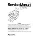
Read Panasonic KX-FL543RU Service Manual online
KX-FL543RU
(for Russia )
(for Ukraine)
High Speed Laser Fax and Copier
IMPORTANT INFORMATION ABOUT LEAD FREE, (PbF), SOLDERING
If lead free solder was used in the manufacture of this product the printed circuit boards will be marked PbF.
Standard leaded, (Pb), solder can be used as usual on boards without the PbF mark.
When this mark does appear please read and follow the special instructions described in this manual on the use of PbF and how
it might be permissible to use Pb solder during service and repair work.
it might be permissible to use Pb solder during service and repair work.
ORDER NO. KMF0408800C3
1
INTRODUCTION
4
1.1.
ABOUT LEAD FREE SOLDER (PbF: Pb free)
4
1.2.
HOW TO RECOGNISE THAT Pb FREE SOLDER IS
USED
5
1.3.
TRANSLATION LIST
6
1.4.
SAFETY PRECAUTIONS
9
1.5.
INSULATION RESISTANCE TEST
9
1.6.
FOR SERVICE TECHNICIANS
9
1.7.
BATTERY CAUTION
9
1.8.
AC CAUTION
10
1.9.
PERSONAL SAFETY PRECAUTIONS
10
1.10. SERVICE PRECAUTIONS
12
1.11. FOR BEST PERFORMANCE
12
2
FEATURES AND SPECIFICATIONS
13
2.1.
FEATURES
13
2.2.
SPECIFICATIONS
14
2.3.
OPTIONAL ACCESSORIES
14
3
INSTALLATION
15
3.1.
LOCATION OF CONTROLS
15
3.2.
CONNECTIONS
17
3.3.
INSTALLATION
18
4
MAINTENANCE
29
4.1.
MAINTENANCE ITEMS AND COMPONENT LOCATIONS
29
4.2.
PRINTING
31
4.3.
PRINTING (PAPER PICK UP)
32
4.4.
SCANNING (ADF)
33
4.5.
MAINTENANCE
34
4.6.
DOCUMENT JAMS
37
4.7.
RECORDING PAPER JAMS
38
5
DISASSEMBLY INSTRUCTIONS
41
5.1.
UPPER MAIN CABINET SECTION
42
5.2.
LOWER MAIN CABINET SECTION
43
5.3.
HOW TO REMOVE THE OPERATION PANEL ASS
炭
44
5.4.
HOW TO REMOVE THE PICK UP UNIT
45
5.5.
HOW TO REMOVE THE PICK UP ROLLER
46
5.6.
HOW TO REMOVE THE OPERATION BOARD
47
5.7.
HOW TO REMOVE THE LOWER FRAME
48
5.8.
HOW TO REMOVE THE SEPARATION RUBBER
48
5.9.
HOW TO REMOVE THE TRANSFER ROLLER
49
5.10. HOW TO REMOVE THE SEPARATION ROLLER
50
5.11. HOW TO REMOVE THE BOTTOM PLATE
51
5.12. HOW TO REMOVE THE ANALOG BOARD
51
5.13. HOW TO REMOVE THE HIGH VOLTAGE POWER
BOARD
52
5.14. HOW TO REMOVE THE LASER UNIT
52
5.15. HOW TO REMOVE THE FAN UNIT
53
5.16. HOW TO REMOVE THE LOW VOLTAGE POWER
BOARD
53
5.17. HOW TO REMOVE THE SOLENOID
54
5.18. HOW TO REMOVE THE MOTOR COVER
54
5.19. HOW TO REMOVE THE MAIN MOTOR
55
5.20. HOW TO REMOVE THE FUSER UNIT
56
5.21. HOW TO REMOVE THE CIS
57
5.22. NOTE FOR ASSEMBLING
58
5.23. INSTALLATION POSITION OF THE LEAD
59
6
TROUBLESHOOTING GUIDE
60
6.1.
USER RECOVERABLE ERRORS
60
6.2.
PROGRAMMING AND LISTS
62
6.3.
TEST FUNCTIONS
66
6.4.
REMOTE PROGRAMMING
70
6.5.
TROUBLESHOOTING DETAILS
78
7
CIRCUIT OPERATIONS
149
7.1.
CONNECTION DIAGRAM
149
7.2.
GENERAL BLOCK DIAGRAM
150
7.3.
FACSIMILE SECTION
152
7.4.
NCU SECTION
163
7.5.
ITS (Integrated telephone System) and MONITOR
SECTION
166
7.6.
CIS CONTROL SECTION
167
7.7.
STEPPING MOTOR DRIVE SECTION
168
7.8.
FAN MOTOR SECTION
172
7.9.
SOLENOID DRIVE SECTION
174
7.10. LSU (Laser Scanning Unit) SECTION
175
7.11. SENSORS AND SWITCHES SECTION
177
7.12. OPERATION BOARD SECTION
186
7.13. LCD SECTION
187
7.14. HVPS (High Voltage Power Supply) SECTION
188
7.15. HEAT LAMP CONTROL CIRCUIT
190
7.16. POWER SUPPLY BOARD SECTION
196
8
REFERENCE MATERIALS DATA
199
8.1.
PRINTING OPERATION PRINCIPLE
199
8.2.
TERMINAL GUIDE OF THE ICs TRANSISTORS AND
DIODES
207
8.3.
HOW TO REPLACE THE FLAT PACKAGE IC
208
8.4.
DIGITAL BOARD SECTION
210
8.5.
MODEM SECTION
212
8.6.
TEST CHART
218
9
FIXTURES AND TOOLS
220
10 CABINET, MECHANICAL AND ELECTRICAL PARTS
LOCATION
221
10.1. GENERAL SECTION
221
10.2. OPERATION COVER SECTION (1)
222
10.3. OPERATION COVER SECTION (2)
223
10.4. OPERATION COVER SECTION (3)
224
10.5. PICK UP SECTION
225
10.6. FUSER SECTION
226
10.7. UPPER MAIN CABINET SECTION
227
10.8. LOWER MAIN CABINET SECTION (1)
228
10.9. LOWER MAIN CABINET SECTION (2)
229
10.10. LOWER CABINET SECTION (3)
230
10.11. ACTUAL SIZE OF SCREWS AND WASHER
231
CONTENTS
Page
Page
2
KX-FL543RU
11 ACCESSORIES AND PACKING MATERIALS
232
12 REPLACEMENT PARTS LIST
233
12.1. CABINET AND ELECTRICAL PARTS
233
12.2. ACCESSORIES AND PACKING MATERIALS
235
12.3. DIGITAL BOARD PARTS
235
12.4. ANALOG BOARD PARTS
238
12.5. OPERATION BOARD PARTS
240
12.6. HIGH VOLTAGE POWER SUPPLY BOARD PARTS 241
12.7. LOW VOLTAGE POWER SUPPLY BOARD PARTS 242
12.8. EXIT SENSOR BOARD PARTS
242
12.9. DRUM AND TONER SENSOR BOARD PARTS
242
12.10. VARISTOR BOARD PARTS
242
12.11. FIXTURES AND TOOLS
243
13 FOR THE SCHEMATIC DIAGRAMS
244
14 SCHEMATIC DIAGRAM
246
14.1. DIGITAL BOARD (PCB1)
246
15 SCHEMATIC DIAGRAM
250
15.1. ANALOG BOARD (PCB2)
250
15.2. OPERATION BOARD (PCB3)
252
15.3. HIGH VOLTAGE POWER SUPPLY BOARD (PCB4) 254
15.4. LOW VOLTAGE POWER SUPPLY BOARD (PCB5) 255
15.5. EXIT SENSOR BOARD (PCB6)
256
15.6. DRUM AND TONER SENSOR BOARD (PCB7)
256
15.7. VARISTOR BOARD (PCB8)
256
16 PRINTED CIRCUIT BOARD
257
16.1. DIGITAL BOARD (PCB1)
257
16.2. ANALOG BOARD (PCB2)
259
16.3. OPERATION BOARD (PCB3)
261
16.4. HIGH VOLTAGE POWER SUPPLY BOARD (PCB4) 263
16.5. LOW VOLTAGE POWER SUPPLY BOARD (PCB5) 265
16.6. EXIT SENSOR BOARD PARTS (PCB6)
267
16.7. DRUM AND TONER SENSOR BOARD (PCB7)
267
16.8. VARISTOR BOARD (PCB8)
267
3
KX-FL543RU
1 INTRODUCTION
1.1. ABOUT LEAD FREE SOLDER (PbF: Pb free)
Note:
In the information below, Pb, the symbol for lead in the periodic table of elements, will refer to standard solder or solder that
contains lead.
contains lead.
We will use PbF solder when discussing the lead free solder used in our manufacturing process which is made from Tin, (Sn),
Silver, (Ag), and Copper, (Cu).
Silver, (Ag), and Copper, (Cu).
This model, and others like it, manufactured using lead free solder will have PbF stamped on the PCB. For service and repair
work we suggest using the same type of solder although, with some precautions, standard Pb solder can also be used.
work we suggest using the same type of solder although, with some precautions, standard Pb solder can also be used.
Caution
·
PbF solder has a melting point that is 50° ~ 70° F, (30° ~ 40°C) higher than Pb solder. Please use a soldering iron with
temperature control and adjust it to 700° ± 20° F, (370° ± 10°C). In case of using high temperature soldering iron, please
be careful not to heat too long.
temperature control and adjust it to 700° ± 20° F, (370° ± 10°C). In case of using high temperature soldering iron, please
be careful not to heat too long.
·
PbF solder will tend to splash if it is heated much higher than its melting point, approximately 1100°F, (600°C).
·
If you must use Pb solder on a PCB manufactured using PbF solder, remove as much of the original PbF solder as possible
and be sure that any remaining is melted prior to applying the Pb solder.
and be sure that any remaining is melted prior to applying the Pb solder.
·
When applying PbF solder to double layered boards, please check the component side for excess which may flow onto the
opposite side (See figure, below).
opposite side (See figure, below).
1.1.1. SUGGESTED PBF SOLDER
There are several types of PbF solder available commercially. While this product is manufactured using Tin, Silver, and Copper,
(Sn+Ag+Cu), you can also use Tin and Copper, (Sn+Cu), or Tin, Zinc, and Bismuth, (Sn+Zn+Bi). Please check the manufac-
turer’s specific instructions for the melting points of their products and any precautions for using their product with other
materials.
The following lead free (PbF) solder wire sizes are recommended for service of this product: 0.3mm, 0.6mm and 1.0mm.
4
KX-FL543RU

