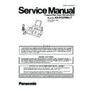
Read Panasonic KX-FC278RU Service Manual online
ORDER NO. KMF0910257CE
Compact Plain Paper FAX with DECT
Model No.
KX-FC278RU-T
Titanium Black version
(for Russia)
(for Russia)
2
KX-FC278RU-T
TABLE OF CONTENTS
PAGE
PAGE
1 Safety Precautions -----------------------------------------------5
1.1. For Service Technicians ----------------------------------5
1.2. AC Caution---------------------------------------------------5
1.3. Personal Safety Precautions ----------------------------6
1.2. AC Caution---------------------------------------------------5
1.3. Personal Safety Precautions ----------------------------6
1.3.1. Moving Sections of the Unit-------------------------6
1.3.2. Live Electrical Sections ------------------------------6
1.3.2. Live Electrical Sections ------------------------------6
1.4. Service Precautions ---------------------------------------7
1.4.1. Precautions to Prevent Damage from
Static Electricity ----------------------------------------7
2 Warning --------------------------------------------------------------8
2.1. About Lead Free Solder (PbF: Pb free) --------------8
2.1.1. Suggested PbF Solder -------------------------------8
2.2. Discarding of P. C. Board --------------------------------8
2.3. Insulation Resistance Test -------------------------------9
2.4. Battery Caution ---------------------------------------------9
2.3. Insulation Resistance Test -------------------------------9
2.4. Battery Caution ---------------------------------------------9
3 Specifications ---------------------------------------------------- 10
3.1. Base Unit --------------------------------------------------- 10
3.2. Cordless Handset ---------------------------------------- 11
3.3. Charger Unit ----------------------------------------------- 11
3.2. Cordless Handset ---------------------------------------- 11
3.3. Charger Unit ----------------------------------------------- 11
4 General/Introduction ------------------------------------------- 12
4.1. Optional Accessories------------------------------------ 12
4.2. Translation Lists ------------------------------------------ 12
4.2. Translation Lists ------------------------------------------ 12
4.2.1. Base Unit ---------------------------------------------- 12
4.2.2. Cordless Handset ----------------------------------- 13
4.2.2. Cordless Handset ----------------------------------- 13
5 Features ------------------------------------------------------------ 14
6 Technical Descriptions---------------------------------------- 15
6 Technical Descriptions---------------------------------------- 15
6.1. Connection Diagram------------------------------------- 15
6.2. General Block --------------------------------------------- 16
6.2. General Block --------------------------------------------- 16
6.2.1. General Block Diagram ---------------------------- 17
6.3. Control (Facsimile) Section---------------------------- 18
6.3.1. ASIC (IC10) ------------------------------------------- 18
6.3.2. Flash Memory (IC16) ------------------------------- 18
6.3.3. Dynamic RAM (IC17)------------------------------- 18
6.3.4. Reset Circuit (Watch Dog Timer) ---------------- 19
6.3.5. Supervision Circuit for the Terminal Head
6.3.2. Flash Memory (IC16) ------------------------------- 18
6.3.3. Dynamic RAM (IC17)------------------------------- 18
6.3.4. Reset Circuit (Watch Dog Timer) ---------------- 19
6.3.5. Supervision Circuit for the Terminal Head
Temperature ------------------------------------------ 20
6.4. Facsimile Section ---------------------------------------- 21
6.4.1. Image Data Flow During Facsimile
Operation ---------------------------------------------- 21
6.4.2. Block Diagram---------------------------------------- 22
6.4.3. Thermal Head ---------------------------------------- 23
6.4.4. Scanning Block -------------------------------------- 25
6.4.5. Stepping Motor Drive Circuit---------------------- 26
6.4.3. Thermal Head ---------------------------------------- 23
6.4.4. Scanning Block -------------------------------------- 25
6.4.5. Stepping Motor Drive Circuit---------------------- 26
6.5. Sensor and Switches------------------------------------ 28
6.5.1. Document Top Sensor (SW351)----------------- 29
6.5.2. Document Set Sensor (SW352) ----------------- 29
6.5.3. Paper Top Sensor (SW1001)--------------------- 30
6.5.4. Cover Open Sensor (SW1001) ------------------ 30
6.5.5. Film End Sensor (SW1003)----------------------- 31
6.5.6. Motor Position Sensor (SW1004) --------------- 31
6.5.7. Hook Switch (SW1501) ---------------------------- 32
6.6. Modem Section ------------------------------------------- 33
6.6.1. Function------------------------------------------------ 33
6.6.2. Modem Circuit Operation-------------------------- 39
6.6.2. Modem Circuit Operation-------------------------- 39
6.7. NCU Section----------------------------------------------- 40
6.7.1. General ------------------------------------------------ 40
6.7.2. Bell Detection Circuit ------------------------------ 40
6.7.3. On/Off Hook Circuit --------------------------------- 40
6.7.2. Bell Detection Circuit ------------------------------ 40
6.7.3. On/Off Hook Circuit --------------------------------- 40
6.7.4. Pulse Dial Circuit------------------------------------ 40
6.7.5. Line Amplifier and Side Tone Circuit ----------- 40
6.7.6. CPC (Calling Party Control) Detection
6.7.5. Line Amplifier and Side Tone Circuit ----------- 40
6.7.6. CPC (Calling Party Control) Detection
Circuit ------------------------------------------------- 40
6.7.7. Auto Disconnect Circuit --------------------------- 41
6.7.8. Calling Line Identification Circuit (Russian
6.7.8. Calling Line Identification Circuit (Russian
CID) ---------------------------------------------------- 42
6.8. ITS (Integrated Telephone System) and
Monitor Section ------------------------------------------ 43
6.8.1. Speakerphone Circuit ------------------------------ 43
6.9. Transmitter / Receiver (Cordless) ------------------- 43
6.9.1. Transmitter Block ----------------------------------- 43
6.9.2. Receiver Block--------------------------------------- 43
6.9.2. Receiver Block--------------------------------------- 43
6.10. Operation Board Section ------------------------------ 44
6.11. LCD Section----------------------------------------------- 45
6.12. Power Supply Board Section ------------------------- 46
6.13. Cordless Handset---------------------------------------- 49
6.13. Cordless Handset---------------------------------------- 49
6.13.1. Block Diagram --------------------------------------- 49
6.13.2. Circuit Operation (Cordless Handset) --------- 50
6.13.3. Circuit Operation (Charger Unit) ---------------- 51
6.13.2. Circuit Operation (Cordless Handset) --------- 50
6.13.3. Circuit Operation (Charger Unit) ---------------- 51
7 Location of Controls and Components ----------------- 52
7.1. Overview --------------------------------------------------- 52
7.1.1. Base Unit---------------------------------------------- 52
7.1.2. Cordless Handset----------------------------------- 52
7.1.2. Cordless Handset----------------------------------- 52
7.2. Control Panel --------------------------------------------- 53
7.2.1. Base Unit---------------------------------------------- 53
7.2.2. Cordless Handset----------------------------------- 54
7.2.2. Cordless Handset----------------------------------- 54
8 Installation Instructions -------------------------------------- 56
8.1. Installation Space ---------------------------------------- 56
8.2. Connections----------------------------------------------- 56
8.2. Connections----------------------------------------------- 56
8.2.1. Base Unit---------------------------------------------- 56
8.2.2. Charger Unit------------------------------------------ 57
8.2.2. Charger Unit------------------------------------------ 57
8.3. Battery Charge ------------------------------------------- 57
8.4. Installing the Ink film ------------------------------------ 58
8.5. Installing the Paper Tray ------------------------------- 59
8.6. Installing the Recording Paper ----------------------- 60
8.7. Battery Installation / Replacement------------------- 61
8.4. Installing the Ink film ------------------------------------ 58
8.5. Installing the Paper Tray ------------------------------- 59
8.6. Installing the Recording Paper ----------------------- 60
8.7. Battery Installation / Replacement------------------- 61
9 Operating Instructions---------------------------------------- 61
9.1. Setting Your Logo---------------------------------------- 61
9.2. Cordless Handset Programming--------------------- 62
9.2. Cordless Handset Programming--------------------- 62
9.2.1. Cordless Handset Features ---------------------- 62
10 Test Mode --------------------------------------------------------- 64
10.1. Facsimile Section---------------------------------------- 64
10.1.1. Button Code Table ---------------------------------- 65
10.1.2. Print Test Pattern------------------------------------ 66
10.1.2. Print Test Pattern------------------------------------ 66
11 Service Mode----------------------------------------------------- 67
11.1. Base Unit -------------------------------------------------- 67
11.1.1. Programming and Lists---------------------------- 67
11.2. Cordless Handset---------------------------------------- 71
11.3. The Example of the Printed List --------------------- 73
11.3. The Example of the Printed List --------------------- 73
11.3.1. User Mode ------------------------------------------- 73
11.3.2. Service Mode Settings ---------------------------- 74
11.3.3. History ------------------------------------------------- 75
11.3.2. Service Mode Settings ---------------------------- 74
11.3.3. History ------------------------------------------------- 75
12 Troubleshooting Guide --------------------------------------- 77
12.1. Troubleshooting Summary ---------------------------- 77
12.1.1. Precautions------------------------------------------- 77
12.2. Error Messages-Display ------------------------------- 78
12.2.1. Base Unit---------------------------------------------- 78
3
KX-FC278RU-T
12.2.2. Cordless Handset------------------------------------80
12.3. Error Messages-Report ---------------------------------81
12.3.1. Journal Report----------------------------------------81
12.3.2. Special Service Journal Reports -----------------90
12.3.3. Communication Section----------------------------93
12.3.2. Special Service Journal Reports -----------------90
12.3.3. Communication Section----------------------------93
12.4. Remote Programming --------------------------------- 102
12.4.1. Entering the Remote Programming Mode
and Changing Service Codes ------------------ 102
12.4.2. Program Mode Table------------------------------ 103
12.5. Troubleshooting Details ------------------------------- 106
12.5.1. Outline ------------------------------------------------ 106
12.5.2. Starting Troubleshooting ------------------------- 106
12.5.3. Troubleshooting Items Table -------------------- 107
12.5.4. ADF (Auto Document Feed) Section --------- 109
12.5.5. Digital Board Section------------------------------ 122
12.5.6. Analog Board Section ---------------------------- 129
12.5.7. Power Supply Board Section ------------------- 131
12.5.8. Operation Panel Section ------------------------- 134
12.5.9. Sensor Section ------------------------------------- 135
12.5.10. CIS (Contact Image Sensor) Section --------- 137
12.5.11. Thermal Head Section---------------------------- 138
12.5.12. Cordless Section----------------------------------- 139
12.5.13. Troubleshooting by Symptom (Cordless
12.5.13. Troubleshooting by Symptom (Cordless
Handset) --------------------------------------------- 143
12.5.14. Troubleshooting by Symptom (Charger
Unit) --------------------------------------------------- 146
13 Service Fixture & Tools-------------------------------------- 147
14 Disassembly and Assembly Instructions ------------- 148
14 Disassembly and Assembly Instructions ------------- 148
14.1. General Section----------------------------------------- 148
14.2. Disassembly Flowchart ------------------------------- 149
14.2. Disassembly Flowchart ------------------------------- 149
14.2.1. Upper Cabinet Section --------------------------- 149
14.2.2. Lower Cabinet Section --------------------------- 149
14.2.3. Back Cover Section ------------------------------- 150
14.2.4. Operation Panel Section ------------------------- 150
14.2.5. Cordless Handset Section----------------------- 151
14.2.6. Charger Section------------------------------------ 151
14.3. Disassembly Procedure------------------------------- 152
14.3.1. How to Remove the Image Sensor (CIS)---- 152
14.3.2. How to Remove the Thermal Head ----------- 153
14.3.3. How to Remove the Bottom Frame ----------- 155
14.3.4. How to Remove the P.C. Boards and
14.3.2. How to Remove the Thermal Head ----------- 153
14.3.3. How to Remove the Bottom Frame ----------- 155
14.3.4. How to Remove the P.C. Boards and
Speaker ---------------------------------------------- 156
14.3.5. How to Remove the Power Supply Board
and AC Cord ---------------------------------------- 157
14.3.6. How to Remove the Gear Block and
Separation Roller ---------------------------------- 158
14.3.7. How to Remove the Gears, Motors and
Arms of the Gear Block -------------------------- 159
14.3.8. How to Remove the Cradle and Hook
Switch Board---------------------------------------- 161
14.3.9. How to Remove the Back Cover--------------- 162
14.3.10. How to Remove the Platen Roller and
Lock Lever------------------------------------------- 163
14.3.11. How to Remove the Pickup Roller and
Antenna ---------------------------------------------- 165
14.3.12. How to Remove the Operation Panel -------- 166
14.3.13. How to Remove the Operation Board, MIC
14.3.13. How to Remove the Operation Board, MIC
Board and LCD------------------------------------- 167
14.3.14. How to Remove the Separation Holder
and Exit Roller -------------------------------------- 168
14.3.15. Installation Position of the Lead Wires ------- 169
14.3.16. How to Remove the Cordless Handset
Board ------------------------------------------------- 175
14.3.17. How to Remove the Charger Board ---------- 177
15 Measurements and Adjustments ------------------------ 178
15.1. Cordless Base Section (Digital Board)
Adjustment----------------------------------------------- 178
15.1.1. Equipment Required ----------------------------- 178
15.1.2. PC Setting------------------------------------------- 178
15.1.3. How to Adjust -------------------------------------- 179
15.1.4. Frequency and Voltage Adjustment ---------- 180
15.1.2. PC Setting------------------------------------------- 178
15.1.3. How to Adjust -------------------------------------- 179
15.1.4. Frequency and Voltage Adjustment ---------- 180
15.2. Adjustment Standard (Base Unit) ------------------ 182
15.2.1. Component View ---------------------------------- 182
15.2.2. Bottom view----------------------------------------- 183
15.2.2. Bottom view----------------------------------------- 183
15.3. Adjustment Standard (Charger Unit) -------------- 184
15.3.1. Bottom View ---------------------------------------- 184
15.4. The Setting Method of JIG (Cordless
Handset)-------------------------------------------------- 185
15.4.1. Preparation------------------------------------------ 185
15.4.2. PC Setting------------------------------------------- 185
15.4.2. PC Setting------------------------------------------- 185
15.5. Adjustment Standard (Cordless Handset) ------- 187
15.5.1. Component View ---------------------------------- 187
15.6. Things to Do after Replacing IC -------------------- 188
15.6.1. Base Unit -------------------------------------------- 188
15.6.2. Cordless Handset --------------------------------- 188
15.6.2. Cordless Handset --------------------------------- 188
15.7. RF Specification ---------------------------------------- 190
15.7.1. Base Unit -------------------------------------------- 190
15.7.2. Cordless Handset --------------------------------- 190
15.7.2. Cordless Handset --------------------------------- 190
15.8. How to Check the Cordless Handset Speaker
or Receiver ---------------------------------------------- 191
15.9. Frequency Table (MHz)------------------------------- 191
16 Maintenance ---------------------------------------------------- 192
16.1. Maintenance Items and Component Locations- 192
16.1.1. Outline ----------------------------------------------- 192
16.1.2. Maintenance Check Items/Component
16.1.2. Maintenance Check Items/Component
Locations -------------------------------------------- 192
16.2. Gear Section -------------------------------------------- 194
16.2.1. Mode Selection ------------------------------------ 194
16.2.2. Mode Operation ----------------------------------- 195
16.2.3. Mechanical Movements in the Main
16.2.2. Mode Operation ----------------------------------- 195
16.2.3. Mechanical Movements in the Main
Operations (transmitting documents,
receiving faxes and copying) ------------------- 198
receiving faxes and copying) ------------------- 198
16.3. Jams------------------------------------------------------- 201
16.3.1. Recording Paper Jams -------------------------- 201
16.3.2. Document Jams ----------------------------------- 202
16.3.2. Document Jams ----------------------------------- 202
16.4. Cleaning -------------------------------------------------- 203
16.4.1. Document feeder/recording paper feeder/
scanner glass cleaning -------------------------- 203
16.4.2. Thermal Head Cleaning ------------------------- 204
17 Miscellaneous-------------------------------------------------- 205
17.1. Terminal Guide of the ICs, Transistors and
Diodes ---------------------------------------------------- 205
17.1.1. Digital Board ---------------------------------------- 205
17.1.2. Analog Board--------------------------------------- 205
17.1.3. Operation Board / Microphone Board -------- 206
17.1.4. Power Supply Board------------------------------ 206
17.1.5. Interface Board ------------------------------------ 206
17.1.6. Cordless Handset Board ------------------------ 207
17.2. How to Replace the Flat Package IC ------------- 208
17.2.1. Preparation------------------------------------------ 208
17.2.2. Flat Package IC Removal Procedure -------- 208
17.2.3. Flat Package IC Installation Procedure------ 209
17.2.2. Flat Package IC Removal Procedure -------- 208
17.2.3. Flat Package IC Installation Procedure------ 209
4
KX-FC278RU-T
17.2.4. Bridge Modification Procedure ----------------- 209
17.3. How to Replace the Shield Case------------------- 210
17.3.1. Preparation------------------------------------------ 210
17.3.2. How to Remove the Shield Case-------------- 210
17.3.3. How to Install the Shield Case ------------------211
17.3.2. How to Remove the Shield Case-------------- 210
17.3.3. How to Install the Shield Case ------------------211
17.4. Test Chart ------------------------------------------------ 212
17.4.1. ITU-T No.1 Test Chart---------------------------- 212
17.4.2. ITU-T No.2 Test Chart---------------------------- 213
17.4.3. Test Chart ------------------------------------------- 214
17.4.2. ITU-T No.2 Test Chart---------------------------- 213
17.4.3. Test Chart ------------------------------------------- 214
18 Schematic Diagram------------------------------------------- 216
18.1. Digital Board (PCB1) ---------------------------------- 216
18.2. Analog Board (PCB2) --------------------------------- 220
18.3. Operation Board (PCB3) / MIC Board (PCB9)-- 222
18.4. Power Supply Board (PCB4)------------------------ 223
18.5. Interface Board (PCB5)------------------------------- 224
18.6. Sensor Board (PCB6)--------------------------------- 225
18.7. Film End Sensor Board (PCB7) -------------------- 225
18.8. Motor Position Sensor Board (PCB8)------------- 225
18.9. Hook Switch Board (PCB10) ------------------------ 225
18.10. Cordless Handset Board (PCB100) --------------- 226
18.11. Charger Board (PCB200) ---------------------------- 228
19 Printed Circuit Board ---------------------------------------- 229
19.1. Digital Board (PCB1) ---------------------------------- 229
19.1.1. Bottom View ---------------------------------------- 229
19.1.2. Component View ---------------------------------- 230
19.1.2. Component View ---------------------------------- 230
19.2. Analog Board (PCB2) --------------------------------- 231
19.2.1. Bottom View ---------------------------------------- 231
19.2.2. Component View ---------------------------------- 232
19.2.2. Component View ---------------------------------- 232
19.3. Operation Board (PCB3) / MIC Board (PCB9)-- 233
19.4. Power Supply Board (PCB4)------------------------ 234
19.5. Interface Board (PCB5)------------------------------- 235
19.6. Sensor Board (PCB6)--------------------------------- 235
19.7. Film End Sensor Board (PCB7) -------------------- 235
19.8. Motor Position Sensor Board (PCB8)------------- 235
19.9. Hook Switch Board (PCB10) ------------------------ 236
19.10. Cordless Handset Board (PCB100) --------------- 237
19.10.1. Component View ---------------------------------- 237
19.10.2. Bottom View ---------------------------------------- 238
19.10.2. Bottom View ---------------------------------------- 238
19.11. Charger Board (PCB200) ---------------------------- 239
19.11.1. Component View ---------------------------------- 239
19.11.2. Bottom View ---------------------------------------- 239
19.11.2. Bottom View ---------------------------------------- 239
20 Appendix Information of Schematic Diagram ------- 240
20.1. For Schematic Diagram ------------------------------ 240
20.2. CPU Data ------------------------------------------------ 241
20.2. CPU Data ------------------------------------------------ 241
20.2.1. IC4: BBIC (Digital Board)------------------------ 241
20.2.2. IC10: ASIC (Digital Board) ---------------------- 242
20.2.3. IC1: BBIC (Cordless Handset Board) -------- 244
20.2.2. IC10: ASIC (Digital Board) ---------------------- 242
20.2.3. IC1: BBIC (Cordless Handset Board) -------- 244
21 Exploded View and Replacement Parts List --------- 246
21.1. Cabinet, Mechanical and Electrical Parts
Location--------------------------------------------------- 246
21.1.1. General Section------------------------------------ 246
21.1.2. Operation Panel Section------------------------- 247
21.1.3. Upper Cabinet Section --------------------------- 248
21.1.4. Back Cover Section------------------------------- 249
21.1.5. Lower Cabinet Section --------------------------- 251
21.1.6. Gear Block Section ------------------------------- 252
21.1.7. Cordless Handset Section ---------------------- 254
21.1.8. Charger Section ----------------------------------- 255
21.1.9. Screws ---------------------------------------------- 256
21.1.10. Accessories and Packing Materials----------- 257
21.2. Replacement Parts List ------------------------------- 258
21.2.1. Cabinet and Mechanical Parts------------------258
21.2.2. Digital Board Parts---------------------------------260
21.2.3. Analog Board Parts--------------------------------263
21.2.4. Operation Board Parts----------------------------263
21.2.5. Power Supply Board Parts ----------------------264
21.2.6. Interface Board Parts -----------------------------264
21.2.7. Sensor Board Parts ------------------------------- 265
21.2.8. Film End Sensor Board Parts-------------------265
21.2.9. Motor Position Sensor Board Parts -----------265
21.2.10. Microphone Board Parts -------------------------265
21.2.11. Hook Swicth Board Parts ------------------------265
21.2.12. Cordless Handset Board Parts -----------------265
21.2.13. Charger Board Parts ------------------------------266
21.2.14. Service Fixture and Tools ------------------------266
21.2.13. Charger Board Parts ------------------------------266
21.2.14. Service Fixture and Tools ------------------------266

