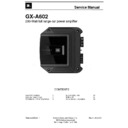
Read JBL GX-A602 Service Manual online
Service Manual
GX-A602
280-Watt full range car power amplifier
Released EU2014
Harman Consumer Group, Inc.
Rev 0, 00/20XX
8500 Balboa Boulevard
OWNER’S MANUAL
2
TROUBLESHOOTING
7
TECHNICAL SPECIFICATIONS
9
BLOCK DIAGRAM
10
BOM LIST
11
SCHEMATIC DIAGRAMS
18
CONTENTS
www.jbl.com
E
ng
lis
h
5
ground (gnd) connectIon
Connect a wire (minimum 10 AWG – 5.3 mm
2
)
from the amplifier’s GND terminal directly to a
solid point on the vehicle’s chassis.
• For a good connection, use sandpaper to clear
• For a good connection, use sandpaper to clear
the paint from the metal surface at this chassis
location. Use a star-type lock washer to secure
the wire’s connection.
poWer (12 V) connectIon
1. Connect a wire (minimum 10 AWG – 5.3 mm
2
)
directly to the battery’s positive (+) terminal.
2. Install a fuse holder for a 50 A fuse (GX-A604,
GX-A3001) or a 30 A fuse (GX-A602) on this
wire within 18" (46 cm) of the battery’s (+)
terminal. Do not install the fuse in the holder
at this time.
3. Route this wire to the amplifier’s location and
connect it to the amplifier’s +12 V terminal.
Be sure to use appropriate grommets
whenever routing wires through the firewall
or other sheet metal.
IMPORTANT: Failure
to adequately protect the positive wire from
potential damage may result in a vehicle fire.
4. When you are finished routing and connecting
this wire, install the appropriate fuse in the
holder you installed near the battery.
(GX-A604, GX-A3001 – 50 A fuse;
GX-A602 – 30 A fuse)
Power
Connectors
Audio System
Head Unit
Chassis Ground
(bare metal)
50 A Fuse (GX-A604/GX-A3001)
30 A Fuse (GX-A602)
18" (46 cm)
Remote Turn-On
(optional)
>#18 AWG (0.82 mm
2
) Wire
>#10 AWG (5.26 mm
2
) Wire
>#10 AWG (5.26 mm
2
) Wire
12
usIng the speaker-leVel Inputs
If your source unit doesn’t have line-level outputs you can use the included speaker-level input harness to connect
the amplifier to the source unit’s speaker outputs. From left to right, the conductors are: L+, L–, R–, R+ (see the
illustration to the right). The speaker-level connectors on all GX-series amp models follow this wiring configuration.
Follow the instructions in the previous sections, substituting the speaker-level connectors for the line-level
Follow the instructions in the previous sections, substituting the speaker-level connectors for the line-level
connectors.
gX-a602 speaker connectIons; 2-channel operatIon
Minimum speaker impedance: 2 ohms (each)
Connect the left and right speakers to the FL and FR (+) and (–) terminals.
Connect the left and right speakers to the FL and FR (+) and (–) terminals.
Fuse 25A
+12V
Speaker
Front Left Speaker
Front Right Speaker
www.jbl.com
E
ng
lis
h
13
gX-a602 Input connectIons: 2-channel operatIon
Connect your source unit or processor’s line outputs as shown in the illustration below.
L+L–R–R+
Line Outputs
Source Unit
See Set The Crossover Controls, on page 20, for information about setting the amplifier’s controls for 2-channel operation.
To use the speaker level inputs instead of the line-level inputs, see Using The Speaker-Level Inputs, on page 12.

