Read JBL ON STAGE III IIIP (serv.man7) EMC - CB Certificate online
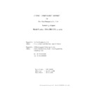
Audix Technology (Shenzhen) Co., Ltd. Report No. ACS-E07439 page 1 of 66
EMC TEST REPORT
For
Harman Multimedia DBA Harman Motive Inc.
Computer Speaker System
Model Number Brand Name
jbl on stage lll
JBL
Prepared for :Harman Multimedia DBA Harman Motive Inc.
Prepared By : Audix Technology (Shenzhen) Co., Ltd.
No. 6, Ke Feng Rd., 52 Block,
Shenzhen Science & Industrial Park,
Nantou, Shenzhen, Guangdong, China
Shenzhen Science & Industrial Park,
Nantou, Shenzhen, Guangdong, China
Tel: (0755) 26639496
Report Number : ACS-E07439
Date of Test
Date of Test
: Jul.08~23,
2007
Date of Report
: Jul.26,
2007
Audix Technology (Shenzhen) Co., Ltd. Report No. ACS-E07439 page 2 of 66
TABLE OF CONTENT
Description Page
Test Report Declaration…………………………………………………………….5
1.
SUMMARY OF STANDARDS AND RESULTS...............................................................6
1.1.
Description of Standards and Results ....................................................................................... 6
2.
GENERAL INFORMATION ..............................................................................................7
2.1.
Description of Device (EUT).................................................................................................... 7
2.2.
Tested Supporting System Details ............................................................................................ 8
2.3.
Test Facility ............................................................................................................................ 10
2.4.
Measurement Uncertainty ....................................................................................................... 10
3.
POWER LINE CONDUCTED EMISSION TEST ..........................................................11
3.1.
Test Equipments ..................................................................................................................... 11
3.2.
Block Diagram of Test Setup.................................................................................................. 11
3.3.
Test Standard .......................................................................................................................... 11
3.4.
Power Line Conducted Emission Limit .................................................................................. 11
3.5.
EUT Configuration on Test .................................................................................................... 12
3.6.
Operating Condition of EUT .................................................................................................. 12
3.7.
Test Procedure ........................................................................................................................ 12
3.8.
Conducted Disturbance at Mains Terminals Test Results ...................................................... 13
4.
RADIATED EMISSION TEST .........................................................................................18
4.1.
Test Equipments ..................................................................................................................... 18
4.2.
Block Diagram of Test Setup.................................................................................................. 18
4.3.
Test Standard .......................................................................................................................... 19
4.4.
Radiated Emission Limit......................................................................................................... 19
4.5.
EUT Configuration on Test .................................................................................................... 19
4.6.
Operating Condition of EUT .................................................................................................. 19
4.7.
Test Procedure ........................................................................................................................ 20
4.8.
Radiated Disturbance Test Results ......................................................................................... 20
5.
HARMONIC CURRENT EMISSION TEST...................................................................25
5.1.
Test Equipments ..................................................................................................................... 25
5.2.
Block Diagram of Test Setup.................................................................................................. 25
5.3.
Test Standard .......................................................................................................................... 25
5.4.
Operating Condition of EUT .................................................................................................. 25
5.5.
Test Results............................................................................................................................. 25
6.
VOLTAGE FLUCTUATIONS & FLICKER TEST .......................................................27
6.1.
Test Equipments ..................................................................................................................... 27
6.2.
Block Diagram of Test Setup.................................................................................................. 27
6.3.
Test Standard .......................................................................................................................... 27
6.4.
Operating Condition of EUT .................................................................................................. 27
6.5.
Test Results............................................................................................................................. 27
7.
IMMUNITY PERFORMANCE CRITERIA DESCRIPTION.......................................29
8.
ELECTROSTATIC DISCHARGE IMMUNITY TEST .................................................30
8.1.
Test Equipments ..................................................................................................................... 30
8.2.
Block Diagram of Test Setup.................................................................................................. 30
8.3.
Test Standard .......................................................................................................................... 30
8.4.
Severity Levels and Performance Criterion ............................................................................ 31
8.5.
EUT Configuration ................................................................................................................. 31
8.6.
Operating Condition of EUT .................................................................................................. 31
8.7.
Test Procedure ........................................................................................................................ 31
Audix Technology (Shenzhen) Co., Ltd. Report No. ACS-E07439 page 3 of 66
8.8.
Test Results............................................................................................................................. 31
9.
RF FIELD STRENGTH SUSCEPTIBILITY TEST .......................................................33
9.1.
Test Equipments ..................................................................................................................... 33
9.2.
Block Diagram of Test Setup.................................................................................................. 33
9.3.
Test Standard .......................................................................................................................... 34
9.4.
Severity Levels and Performance Criterion ............................................................................ 34
9.5.
EUT Configuration ................................................................................................................. 34
9.6.
Operating Condition of EUT .................................................................................................. 34
9.7.
Test Procedure ........................................................................................................................ 34
9.8.
Test Results............................................................................................................................. 34
10. ELECTRICAL FAST TRANSIENT/BURST IMMUNITY TEST ................................36
10.1.
Test Equipments ..................................................................................................................... 36
10.2.
Block Diagram of Test Setup.................................................................................................. 36
10.3.
Test Standard .......................................................................................................................... 36
10.4.
Severity Levels and Performance Criterion ............................................................................ 36
10.5.
EUT Configuration ................................................................................................................. 37
10.6.
Operating Condition of EUT .................................................................................................. 37
10.7.
Test Procedure ........................................................................................................................ 37
10.8.
Test Results............................................................................................................................. 37
11. SURGE TEST ......................................................................................................................39
11.1.
Test Equipments ..................................................................................................................... 39
11.2.
Block Diagram of Test Setup.................................................................................................. 39
11.3.
Test Standard .......................................................................................................................... 39
11.4.
Severity Levels and Performance Criterion ............................................................................ 40
11.5.
EUT Configuration ................................................................................................................. 40
11.6.
Operating Condition of EUT .................................................................................................. 40
11.7.
Test Procedure ........................................................................................................................ 40
11.8.
Test Results............................................................................................................................. 40
12. INJECTED CURRENTS SUSCEPTIBILITY TEST ......................................................42
12.1.
Test Equipments ..................................................................................................................... 42
12.2.
Block Diagram of Test Setup.................................................................................................. 42
12.3.
Test Standard .......................................................................................................................... 43
12.4.
Severity Levels and Performance Criterion ............................................................................ 43
12.5.
EUT Configuration ................................................................................................................. 43
12.6.
Operating Condition of EUT .................................................................................................. 43
12.7.
Test Procedure ........................................................................................................................ 43
12.8.
Test Results............................................................................................................................. 43
13. MAGNETIC FIELD IMMUNITY TEST .........................................................................45
13.1.
Test Equipments ..................................................................................................................... 45
13.2.
Block Diagram of Test Setup.................................................................................................. 45
13.3.
Test Standard .......................................................................................................................... 45
13.4.
Severity Levels and Performance Criterion ............................................................................ 46
13.5.
EUT Configuration on Test .................................................................................................... 46
13.6.
Operating Condition of EUT .................................................................................................. 46
13.7.
Test Procedure ........................................................................................................................ 46
13.8.
Test Results............................................................................................................................. 46
14. VOLTAGE DIPS AND INTERRUPTIONS TEST..........................................................48
14.1.
Test Equipment ....................................................................................................................... 48
14.2.
Block Diagram of Test Setup.................................................................................................. 48
14.3.
Test Standard .......................................................................................................................... 48
14.4.
Severity Levels and Performance Criterion ............................................................................ 49
14.5.
EUT Configuration ................................................................................................................. 49
14.6.
Operating Condition of EUT .................................................................................................. 49
14.7.
Test Procedure ........................................................................................................................ 49
14.8.
Test Results............................................................................................................................. 49
15. PHOTOGRAPH ..................................................................................................................51
Audix Technology (Shenzhen) Co., Ltd. Report No. ACS-E07439 page 4 of 66
15.1.
Photos of Conducted Disturbance at Mains Terminals Test................................................... 51
15.2.
Photos of Radiated Disturbance Test (In 10m Anechoic Chamber) ....................................... 52
15.3.
Photo of Harmonic / Flicker Test............................................................................................ 54
15.4.
Photos of Electrostatic Discharge Immunity Test................................................................... 54
15.5.
Photo of RF Strength Susceptibility Test ............................................................................... 55
15.6.
Photo of Electrical Fast Transient/Burst Immunity Test ........................................................ 56
15.7.
Photo of Surge Test................................................................................................................. 56
15.8.
Photo of Injected Currents Susceptibility Test ....................................................................... 57
15.9.
Photo of Magnetic Field Test.................................................................................................. 57
15.10.
Photo of Voltage Dips and interruptions test.......................................................................... 58
16. PHOTOGRAPHS OF EUT ................................................................................................59

