Read JBL HARMONY (serv.man2) Technical Bulletin online
JBL Incorporated 250 Crossways Park Dr. Woodbury, New York 11797 (516) 496-3400
Service Bulletin
Service Bulletin JBL9804 - August 1998
To:
All JBL Service Centers
Model: Harmony
Subject: Disassembly Procedure
Note: It is very important that the various screws do not get mixed up and inserted in other locations upon
reassembly. Make note or label each removed screw set; keep them apart from other screw sets.
reassembly. Make note or label each removed screw set; keep them apart from other screw sets.
ACCESS TO DRIVERS AND CD ASSEMBLY
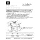
1) Unplug all cables & connectors; place the unit on padded surface.
2) Carefully pry the speaker grille out of its recess and remove. Drivers are now accessible by removal of
2) Carefully pry the speaker grille out of its recess and remove. Drivers are now accessible by removal of
their perspective Phillips screws.
3) At the rear of the unit, remove the (4) screws holding the top cover on. Two are directly underneath the
handle and two are near the center of the unit.
4) Slide the top cover straight back and off the unit, exposing the CD mechanism.
5) At the front of the unit directly below the CD tray, remove the two CD mounting screws.
6) Pull the CD mechanism out and away from the unit. Looking at the rear of the unit, the right side will pull
5) At the front of the unit directly below the CD tray, remove the two CD mounting screws.
6) Pull the CD mechanism out and away from the unit. Looking at the rear of the unit, the right side will pull
away first and “pivot” around a thick wire cluster on the left side of the cabinet.
7) Unplug all connectors; make note of colors and locations - do not mix upon reassembly.
8) To separate CD assembly from PCB:
8) To separate CD assembly from PCB:
a)
Remove the two lower, outermost screws from the small heatsink.
b)
Remove the (4) silver-colored screws from the bottom of the PCB.
c)
Remove the single screw from the RCA jack bracket.
d)
Unplug remaining connectors.
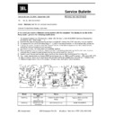
ACCESS TO POWER SUPPLY/LINE FUSES/OTHER PCB’S
1) Follow steps 1
−
7 above.
2) Remove the (8) remaining screws on the front of the cabinet. Note: Two of the screws near the center of
the unit are in deep recesses in the center of the grille pin “catch cups”.
3) At the rear of the unit, remove the two upper corner cabinet screws.
4) Remove the two screws formally underneath the CD assembly at the top of the unit.
5) Carefully pry the front and rear cabinet halves apart; use caution and work carefully around both sides
4) Remove the two screws formally underneath the CD assembly at the top of the unit.
5) Carefully pry the front and rear cabinet halves apart; use caution and work carefully around both sides
evenly to avoid marring the cabinet edges & finish.
6) Remove all connectors necessary for access.
•
Low-voltage AC fuse F903 can be seen on a small PCB attached to the rear of the left midrange driver.
•
The main AC line fuse and +12VDC fuses F901,902 are mounted on a small PCB located on the inside
cavity of the rear cabinet.
cavity of the rear cabinet.
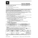
To access the AC Line Fuse, the 12VDC Fuse and Q901:
After main case is separated following all steps above, remove all molex connectors holding cases together.
Remove plastic base on main case (4 screws); then remove the two heatsink screws underneath it.
At the rear of the case, near the AC plug, remove the two plated screws.
Lift both connected PCB’s and heatsink up and out of the case.
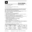
Reassembly -
•
Screws
−
it is very important that the various screws do not get mixed up and inserted in the wrong
locations upon reassembly.
•
Make sure all gaskets & sealing surfaces are intact when cabinet halves are reassembled
−
otherwise, air
leaks may result.
Display

