Read JBL ESC 300 Sub (serv.man15) Technical Bulletin online
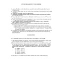
SUB 300 DISASSEMBLY PROCEDURE
1) Unplug all cables; lay the subwoofer on a padded surface so that plastic cabinet base is
facing upwards.
2) Remove (4) oblong rubber feet from cabinet base, exposing the (4) recessed screws holding
the base on.
3) Remove the (4) screws; remove the cabinet base.
4) Remove the (8) woofer mounting screws and remove the woofer; unplug the main speaker
4) Remove the (8) woofer mounting screws and remove the woofer; unplug the main speaker
wires from the terminals.
5) Remove the (10) ¾” machine screws holding the heatsink in place; remove only the screws
on the outer perimeter.
6) Reach into the woofer opening and unplug the (5) two conductor molex connectors from the
Pro Logic board mounted on the inside of the cabinet.
7) Remove both the heatsink (with power supply and main amplifiers) out of the cabinet;
unplug additional connectors as necessary.
8) Normally the input/output plate (with power cord & switch) will not have to be removed;
however, if necessary for the repair:
a) Remove the (8) ¾” machine screws holding the input/output plate on the cabinet.
b) Remove the plate; use caution because one of the 3 conductor cables connecting to
b) Remove the plate; use caution because one of the 3 conductor cables connecting to
the Pro Logic board is very short; unplug it from its molex connector. Unplug all other
connectors as needed.
connectors as needed.
9) If complete removal is desired of the both the amplifier and the input/output plate, the main 2
conductor power wires will have to be separated (cut) or the wire nuts removed near the
power transformer.
power transformer.
REASSEMBLY
Use a backwards sequence from the above steps, some additional notes include:
1) If the input/output plate was removed, make sure the speaker wires exiting the plastic cover
are still air-tight; seal with additional hot glue or silicon seal if necessary.
2) Make sure all connectors, molex, power cord, and woofer wires, are attached and plugged
in their original locations. Observe polarity on woofer wires
−
red wire to red dot on woofer.
You will need to work through the woofer opening for some of the last connections, so the
woofer will be inserted later. Connections for the final (5) 2 conductor molex connectors
are:
woofer will be inserted later. Connections for the final (5) 2 conductor molex connectors
are:
a) CN804
−
Red wire
b) CN701
−
Black wire
c) CN702
−
White wire
d) CN504
−
Gray wire
e) CN503
−
Brown wire
3) Last step is to re-fit plastic base to cabinet, reattach with screws, re-fit rubber plugs.
Display

