Read Harman Kardon CDR 25 (serv.man2) Technical Bulletin online
harman/kardon, Incorporated
250 Crossways Park Dr. Woodbury, New York 11797
harman/kardon
Service Bulletin
Service bulletin # H/K2003-08 October 2003
Warranty labor rate: MINOR repair
To: All harman/kardon Service Centers
Model: CDR25/CDR26
Subject: Skips While Dubbing
In the event you receive a CDR25 or CDR26 with the complaint: “the units skips when dubbing a CD”,
follow the instructions below:
In the event you receive a CDR25 or CDR26 with the complaint: “the units skips when dubbing a CD”,
follow the instructions below:
(Symptom is a random “skipping” or “looping” of program material from the Play deck resulting in a defective recording
when dubbing to CDR disc. Another indication this is taking place is dissimilar track times in the display during recording
(Play vs. Record). All dubbing speeds affected. CD play alone without recording will be normal.)
when dubbing to CDR disc. Another indication this is taking place is dissimilar track times in the display during recording
(Play vs. Record). All dubbing speeds affected. CD play alone without recording will be normal.)
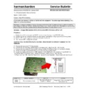
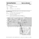
Synopsis: Change SMD resistors R4C4, R4C6 on the MAIN PCB from 2.2
Ω to 1.5Ω
Procedure:
1) Power the unit ON and press the EJECT button to open the tray on the RECORD side.
2) Supporting the tray, carefully remove the gray drawer faceplate by lifting it up and out of the groove.
3) Press EJECT button again to retract the tray back into the unit.
4) Turn the unit OFF, unplug AC line cord.
2) Supporting the tray, carefully remove the gray drawer faceplate by lifting it up and out of the groove.
3) Press EJECT button again to retract the tray back into the unit.
4) Turn the unit OFF, unplug AC line cord.
CAUTION: FOLLOW PROPER STATIC CONTROL PROCEDURES TO PREVENT DAMAGE TO THE
CDR25/26.
CDR25/26.
5) Remove the top cover (7 Phillips screws).
6) Remove the six connector cables/plugs on the Main PCB: PN501,503,401,403,405,406.
7) Remove the four plated Phillips screws holding the Main PCB/Record Ass’y to the bottom chassis.
8) Lift the entire Main PCB/Record Ass’y out of the unit; turn it upside-down.
9) Locate and replace the two 2.2
6) Remove the six connector cables/plugs on the Main PCB: PN501,503,401,403,405,406.
7) Remove the four plated Phillips screws holding the Main PCB/Record Ass’y to the bottom chassis.
8) Lift the entire Main PCB/Record Ass’y out of the unit; turn it upside-down.
9) Locate and replace the two 2.2
Ω SMD resistors R4C4, R4C6 with 1.5Ω resistors, h/k part# 260-1.5.
10) Replace Main PCB/Record Ass’y; replace connectors PN501,503,401,403,405,406.
11) Plug in unit; turn ON. Eject the Record tray; replace the tray faceplate. Close drawer and test the unit.
11) Plug in unit; turn ON. Eject the Record tray; replace the tray faceplate. Close drawer and test the unit.
MODELS
SERIAL NUMBER
STATUS
ACTION
CDR25
CDR26
CDR26
All serial numbers affected
May need modification for
complaint of “skipping”
Change R4C4, R4C6 on the MAIN PCB
from 2.2
Ω to 1.5Ω
Display

