Read Harman Kardon AVR 45 (serv.man6) Technical Bulletin online
harman/kardon Incorporated 250 Crossways Park Drive, Woodbury New York 11797 (516) 496-3400
harman/kardon
Service Bulletin
Service bulletin # H/K9903 August 1999
To:
All harman/kardon Service Centers
Models: AVR35/45/65 Dolby Digital A/V Receivers
Subject: Interference on Television
One of the measurements of a good signal strength, whether it be audio or RF, is called the signal to noise ratio. In
other words, given a set level of interference or noise, the stronger the signal, the less noticeable the noise. Similarly,
when a signal is not as strong as desired, you can attempt to lower the noise to improve the signal.
other words, given a set level of interference or noise, the stronger the signal, the less noticeable the noise. Similarly,
when a signal is not as strong as desired, you can attempt to lower the noise to improve the signal.
Digital products such as newer FAX machines and state of the art audio products like the AVR35, AVR45 and AVR65
often produce more RF interference than traditional analogue designs. The parts and procedure we recommend below
will reduce RF interference, and lower the noise level by improving the signal to noise ratio.
In the event you receive an AVR35, AVR45 or AVR65 Receiver with the complaint “There is video distortion on
my television on certain channels when my TV is attached to my AVR receiver, and I am using an external TV
antenna”, perform the steps listed below. We have also included recommendations which can be made to the
customer.
1) Order h/k part# KT65A which consists of two Ferrite chokes, and 12 new black screws for the rear panel,
h/k part# A123010002.
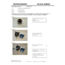
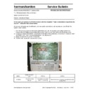
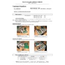
2) Attach the larger of the two ferrite chokes on to the receiver’s power (AC) cord, approximately 2 inches from the
rear panel: Open the block, lay the cord inside, and then wind the power cord around the choke at least 3 times.
Close block.
Close block.
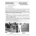
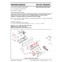
3) Locate the 6 -12 (depending on model) black Phillips screws at the outer rear panel of the unit, only in the area of:
the Video panel, Digital Input panel, Remote control panel, and Pre-Out panel (AVR45 & 65 only). Remove and
replace these screws with h/k part# A123010002. (The new screws have "teeth" on the bottom of the head for
assuring proper contact with rear panel.)
replace these screws with h/k part# A123010002. (The new screws have "teeth" on the bottom of the head for
assuring proper contact with rear panel.)
4) Test
unit.
Further recommendations which can be made to the customer:
1) To limit the interference coming into the cable that goes into the television, clip the smaller ferrite choke (part of kit
KT65A) on to the coaxial antenna cable, about 2 inches from the rear of your television set.
2) Change any #RG-59 coaxial cable going into the television with #RG-06 coaxial cable, which has improved
shielding.
3) Disconnect all power (AC) cords from the convenience (switched or unswitched) AC outlets on the back of the AVR
receiver, as they may behave like antennas.
4) If there is still an unacceptable level of interference, use an antenna amplifier to improve the TV signal strength.
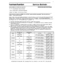
Model
Serial numbers
Screws - action
Ferrite choke from kit# KT65A
AVR35 (120v)
AVR45 (120v)
AVR65 (120v)
AVR45 (120v)
AVR65 (120v)
All serial numbers
All serial numbers
All serial numbers
JS0003-01001
to
JS0003-11078
Replace
Replace
Replace
Replace
Clip on cord
Clip on cord
Clip on cord
Clip on cord
AVR65 (120v)
JS0003-11079
and above
Changed by factory
Installed by factory internally
AVR35 (230v)
AVR45 (230v)
AVR65 (230v)
AVR45 (230v)
AVR65 (230v)
All serial numbers
All serial numbers
All serial numbers
All serial numbers
All serial numbers
Replace
Replace
Replace
Replace
Replace
Installed by factory internally
Installed by factory internally
Installed by factory internally
Installed by factory internally
Installed by factory internally
Display

