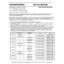
Read Harman Kardon AVR 35 (serv.man14) Technical Bulletin online
harman/kardon Incorporated 250 Crossways Park Drive, Woodbury New York 11797 (516) 496-3400
1
harman/kardon
Service Bulletin
Service bulletin # H/K2001-02 June 2001
Warranty labor rate: MAJOR repair
To: All harman/kardon Service Centers
Models: AVR35/45/65, (US,SG,RDS Models)
Subject: Left, Right, or Center channel Dead
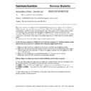
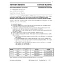
In the event you receive an AVR35, 45, or 65 A/V receiver with the complaint: “One channel has no
output”, check the item below:
One or more of the 10 ohm fusible resistors R445,446,447,448,523, or 524 on the main PCB may be damaged.
Perform with an ohmmeter an in-circuit resistance test of these 6 resistors. The Ohmmeter should read
10 ohms
±10%. If one or more resistors are out of tolerance, all 6 resistors (R445,446,447,448,523,524) should
be changed to 10 ohm 1/4W metal film type, h/k part# 271-10.
1) Disconnect all external cables; remove the top cover (16 Black Phillips screws).
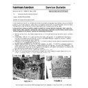
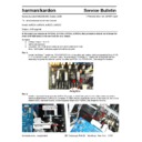
2) See page 2 for exact location of R445,446,447,448,523,524. If any resistors are found out of tolerance, proceed
2) See page 2 for exact location of R445,446,447,448,523,524. If any resistors are found out of tolerance, proceed
with the following steps:
3) Lay unit on its left side on a padded surface; remove the (8) Phillips screws holding the bottom chassis grille on,
which will expose the Main PCB. Remove the two “feet” that are partially covering the grille.
4)
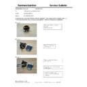
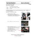
Recommended procedure for resistor replacement is to cut each part off the main PCB from the top, then solder
the replacement part on the bottom of the PCB in the same location. There may be a square foam cushion on the
bottom of the PCB covering the area(s) of one or more resistors pads; remove it. Use caution when correctly
identifying each location, comparing the top and bottom of the main PCB. Tip: Resistors are represented by a
silkscreen on the bottom of the main PCB by this line:
Model
Serial Number
120V
Serial Number
230V
STATUS
ACTION
AVR35
JS0007-01001
to
JS0007-16390
n/a
R445,446,447,448,523,
524 are fusible resistors
If damaged, replace
with 10 ohm 1/4W
metal film resistors
AVR35RDS
n/a
JS0005-01001
to
JS0005-06000
R445,446,447,448,523,
524 are fusible resistors
If damaged, replace
with 10 ohm 1/4W
metal film resistors
AVR35SG
n/a
JS0009-01001
to
JS0009-02537
R445,446,447,448,523,
524 are fusible resistors
If damaged, replace
with 10 ohm 1/4W
metal film resistors
AVR45
JS0001-01001
to
JS0001-12782
n/a
R445,446,447,448,523,
524 are fusible resistors
If damaged, replace
with 10 ohm 1/4W
metal film resistors
AVR45RDS
n/a
JS0004-01001
to
JS0004-04453
R445,446,447,448,523,
524 are fusible resistors
If damaged, replace
with 10 ohm 1/4W
metal film resistors
AVR45SG
n/a
JS0008-01001
to
J30008-02980
R445,446,447,448,523,
524 are fusible resistors
If damaged, replace
with 10 ohm 1/4W
metal film resistors
AVR65
JS0003-01001
to
JS0003-06422
n/a
R445,446,447,448,523,
524 are fusible resistors
If damaged, replace
with 10 ohm 1/4W
metal film resistors
AVR65RDS
n/a
JS0006-01001
to
JS0006-01777
R445,446,447,448,523,
524 are fusible resistors
If damaged, replace
with 10 ohm 1/4W
metal film resistors
AVR65SG
n/a
JS0010-01001
to
JS0010-01464
R445,446,447,448,523,
524 are fusible resistors
If damaged, replace
with 10 ohm 1/4W
metal film resistors
harman/kardon Incorporated 250 Crossways Park Drive, Woodbury New York 11797 (516) 496-3400
2
Display

