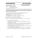
Read Harman Kardon AVR 156 (serv.man3) Technical Bulletin online
1
harman/kardon, Incorporated
8500 Balboa Blvd. Northridge, CA. 91329
harman/kardon
Service Bulletin
Service bulletin # HK2011-01, August 2011
Warranty labor rate: MINOR repair
To: All Harman Kardon Service Centers
Models:
AVR 1565, AVR 1650 (120v)
AVR 156, AVR 158, AVR 165 (230v).
Subject: Distortion in semi-OSD display
In the event you receive an AVR1565, AVR1650 or AVR 156, AVR 158, AVR 165 with the complaint “there
is a Flicker or Distortion in the semi-OSD display on TV when using the Composite Video Monitor out
connection”, follow the procedure below:
Synopsis: Replace components L801 and C106 on the Video PCB Ass'y with new components.
Note: RoHS-rated* de-soldering and soldering equipment will be required.
PARTS REQUIRED: order (1) hk part# 2011AVR-CAPCOILKIT
(The kit consists of L801 part# CLQ03D5R6JT and C106 part# CCCT1H300JC)
Original L801 is 5.6uH 10% coil; replacement is 5.6uH 5% coil.
Original C106 is 33pf ceramic cap; replacement is 30pf ceramic cap.
NOTE: do not use the two original part numbers listed in the service manual, do not use substitute parts.
1. Remove the Top Cover, 13 Phillips screws.
2. Locate and remove both the Video PCB and HDMI PCB, 9 Phillips screws total, which are then
connected together with a header.
3. Separate the Video PCB and HDMI PCB and unplug the 3 pin Molex connector from the Video PCB.
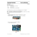
4. On the component side of the Video PCB, locate L801 and C106. Unsolder and replace coil L801;
unsolder and replace capacitor C106. See the illustration on page 2.
5. Replace the 3 pin Molex connector, connect the Video PCB and HDMI PCB together and replace in the
unit; replace all Phillips screws. Replace the top cover.
6. Test by connecting the Composite Video Monitor out to a TV or display. Turn the AVR ON. Press
function buttons on the Remote control to view the semi-OSD display to confirm the text is stable.
2
harman/kardon, Incorporated
8500 Balboa Blvd. Northridge, CA. 91329
Service bulletin # HK2011-01 August 2011
Subject: Distortion in semi-OSD display
* RoHS = Restriction Of Hazardous Substances. Recommended lead free solder 96.5/3.0/0.5
Model
Serial Number (120v)
Serial Number (230v)
Status
Action
AVR 156
AN0122-01000
to
AN0122-03820
May have semi-OSD
distortion
Replace L801 and
C106.
AVR 156
AN0122-03821
and above
None Required
AVR 158
AN0123-01000
to
AN0123-02620
May have semi-OSD
distortion
Replace L801 and
C106.
AVR 158
AN0123-02621
and above
None Required
AVR 165
AN0124-01000
to
AN0124-03920
May have semi-OSD
distortion
Replace L801 and
C106.
AVR 165
AN0124-03921
and above
None Required
AVR 1565
AN0117-01001
to
AN0117-04000
May have semi-OSD
distortion
Replace L801 and
C106.
AVR 1565
AN0117-04001
and above
None Required
AVR 1650
AN0119-01001
to
AN0119-03500
May have semi-OSD
distortion
Replace L801 and
C106.
AVR 1650
AN0119-03501
and above
None Required
Display


